M
OUNTING THE
M
AGNET AND
S
ENSOR
M
OUNTING THE
M
AGNET AND
S
ENSOR
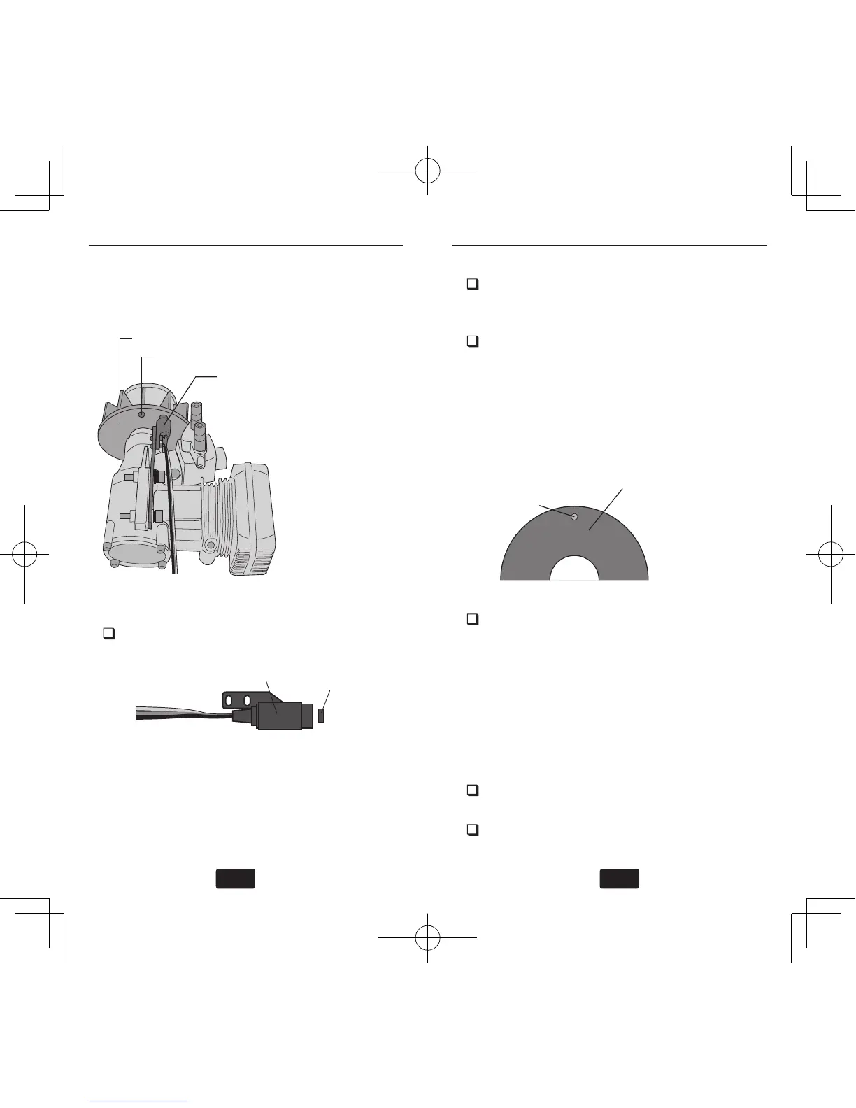
Modify the cooling fan and install the accessory
magnet and attach the magnetic sensor to the en-
gine at the position shown below.
Cooling fan
Magnet (Embedded in cooling fan.)
Sensor (Attached to engine flange
through a stay.)
When installing the sensor mag-
net to the mufer side, also refer
to the needle side mounting.
Cooling fan modication
Drill a hole in the fan at the magnet mount-
ing position. Make the hole about 4.1mm in
diameter and 1.5 to 1.7mm deep.
Embed the magnet in this hole in the direc-
tion in which an output is obtained. Use
epoxy adhesive that cures in 30 minutes or
longer. Do not use epoxies that contain metal
such as JB Weld.
Magnet
Cement the magnet to the cooling
fan so that the magnet is level
with this side of the cooling fan.
If the cooling fan is unbalanced and vibrates,
etc., balance it by mounting the spare magnet
to the opposite side of the cooling fan in the
opposite polarity (so that it does not output a
signal).
Sensor mounting
The sensor mounting method depends on the heli-
copter and engine.
Mount the sensor to the sensor stay. (Tempo-
rary assembly)
Drill a hole in the fan cover at the part cor-
responding to the sensor so that the distance
Magnet operating side check
Bring the magnet near the end of the sensor
and check the operating side.
This is the side at which the displayed value
increases in the “Revolution sensor testing”
menu within the “Governor Basic Setting”
section earlier in this manual. Install the mag-
net with this side facing the sensor. Mark this
side of the magnet with a felt tip pen.