It sets the governor’s fundamental functions. The
menu (9) Servo limit point setting must be set
rst with other menu.
(1) Start display
The editing menu are scrolled ev-
ery pushing the mode + or – key.
(2) Revolution setting
[range: 1000
〜
3000
rpm]
Setting the main rotor revolution. It is calculated
by engine revolution with the gear ratio of the
main shaft.
• Using by 3position switch
Making sure the display is changed to 1, 2, 3 by
moving the switch. Set the desire RPM at each con-
dition by pushing the data + or – key.
• Direct set by transmitter on Gov. mixing
Contained governor mixing like T14MZ and T12FG
function, calibration of the 3 point rst, direct RPM
setting can be available after that.
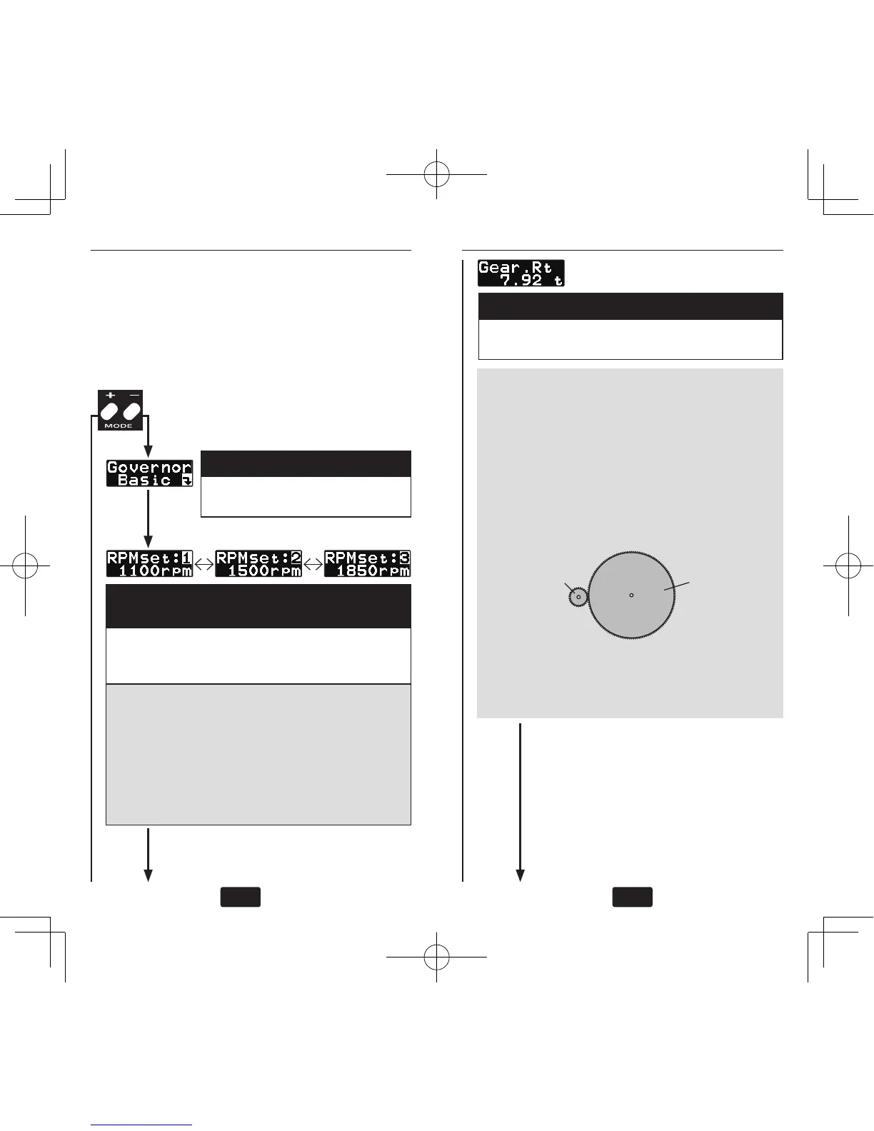
(3) Gear ratio
[default: 8.00, range: 3
〜
30]
Input the main rotor gear ratio by pushing the
data + or-key.
Push MODE
+/– key
Notes:
• If the gear ratio is not properly set, the set
speed and actual engine speed will be differ-
ent.
• The gear ratio should be given in the heli-
copter instruction manual. If the helicopter in-
struction manual does not give the gear ratio,
calculate the gear ratio as follows: