It sets the function to channel at S.Bus connection.
It is required the S.Bus compatible receiver. The
wiring from receiver to servos is to be simple by
using the S.Bus connection, only one main S.Bus
wire is connected to receiver and GY701 can
complete the operation. In addition, governor on/
off switch function, F/F mixing can be available
at the S.Bus connection. At the PWM connection,
this function is invalid. When do not use S.Bus
channel, set “INH” for the channel setting. The
S.Bus channels have linear 16ch, digital 2ch, 18ch
total, but the controllable channels are limited by
the transmitter channels.
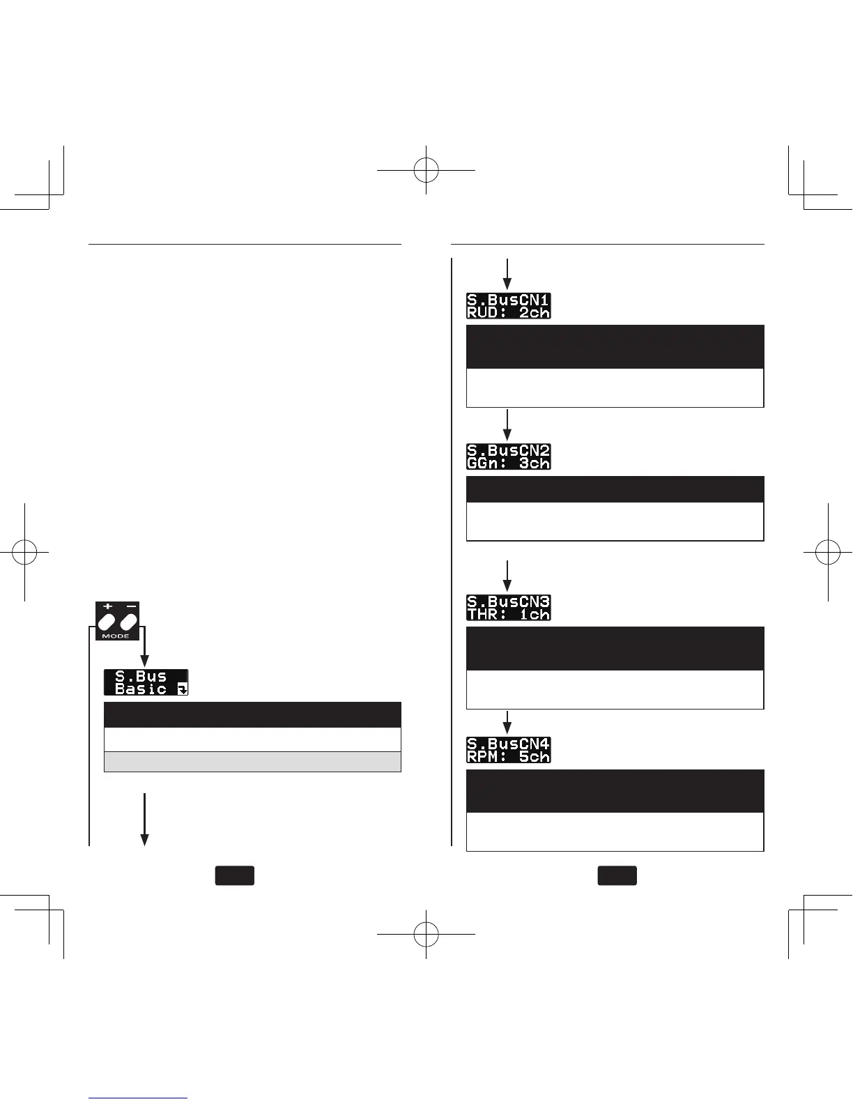
(1) S.Bus connection setting: start display
Mode is changed by pushing mode + or – key.
Setting ranges common: 1
〜
16ch, DG1, DG2
Push MODE
+/– key
(2) S.Bus setting: Rudder channel [default:
4ch]
Push data + or – key to match the transmitter
rudder channel.
(3) S.Bus setting: Gyro gain [default: 5ch]
Push data + or – key to match the transmitter
gyro gain channel.
(4) S.Bus setting: Throttle channel [default:
3ch]
Push data + or – key to match the transmitter
throttle channel.
(5) S.Bus setting: RPM channel [default:
7ch]
Push data + or – key to match the transmitter
RPM setting channel.