Do you have a question about the FUTABA GY701 and is the answer not in the manual?
Overview of the Futaba GY701's capabilities and technology.
Key characteristics and advantages of the GY701 unit.
Explanation of warning symbols and their significance.
Safety guidelines specific to gyro operation.
Safety guidelines specific to governor operation.
Ensuring helicopter mechanics are optimized for gyro/governor.
Initial display sequence upon powering on the GY701.
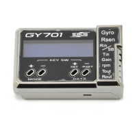
Overview of the main operational screen and its elements.
Indicates the current gyro operating mode (AVCS or Normal).
Shows the set revolution for the governor.
Displays main rotor or engine revolution.
Displays Battery voltage, Max. revolution, Engine runtime, etc.
Selects the display mode for the LED on the gyro sensor.
Sets the operating mode of the GY701 (Gyro, Governor, or both).
Indicates governor warnings like low battery.
Shows no rudder or throttle signal input.
Indicates the gyro sensor is not working correctly.
Explains how to navigate and change settings in the edit menus.
Scans through editing menus by pushing mode keys.
Selects the servo type for the rudder.
Sets the operation direction of the gyro.
Adjusts the maximum servo throw for the rudder.
Selects the flight style (F3C or 3D).
Guidelines for properly mounting the gyro sensor.
Steps for installing and configuring the tail rotor servo.
Essential checks before attempting flight.
Fine-tuning parameters during initial test flights.
Configuration and use of the Normal (Rate) gyro mode.
Procedures for setting gyro gain values for different flight modes.
Scans through editing menus by pushing mode keys.
Sets the main rotor revolution for the governor.
Input the main rotor gear ratio for governor calculations.
Selects the throttle servo type for optimal response.
Activates governor via throttle stick position.
Selects the switch for activating the governor.
Configures governor behavior during low battery conditions.
Sets the throttle servo maximum through.
Tests the output level of the revolution sensor.
Modifying the cooling fan for magnet installation.
Methods for mounting the governor sensor.
Adjusting sensor position for optimal output.
Precautions for throttle servo linkage for governor use.
Addresses vibrations affecting governor performance.
Explanation of how the governor stabilizes engine speed.
Requirements for the governor to activate.
Procedures for setting desired engine speeds for the governor.
Precautions for setting speed channels and maximum limits.
Configuration for S.Bus connection and channel assignments.
Assigns the rudder channel for S.Bus connection.
Assigns the gyro gain channel for S.Bus connection.
Assigns the throttle channel for S.Bus connection.
Assigns the RPM channel for S.Bus connection.
Assigns the governor on/off channel for S.Bus.
Assigns the pitch channel for S.Bus connection.
Sets the fundamental gain for the gyro.
Sets the control feeling of the rudder.
Adjusts the pirouette speed by rudder control.
Selects F/F (Feed Forward) mixing active.
Sets the minimum pitch point of GY701.
Selects governor mode (Governor or Revolution Limit).
Selects governor operation response based on engine type.
Sets the governor working gain.
Selects throttle input operation (Optimize, Fixed, Tx.Curve).
| Application | RC Helicopters |
|---|---|
| Operating Voltage | 4.8V - 8.4V |
| Governor Function | Yes |
| Type | Gyro |
| Sensors | 3-axis |
| Connector Type | Standard servo connectors |
| Compatibility | Futaba |