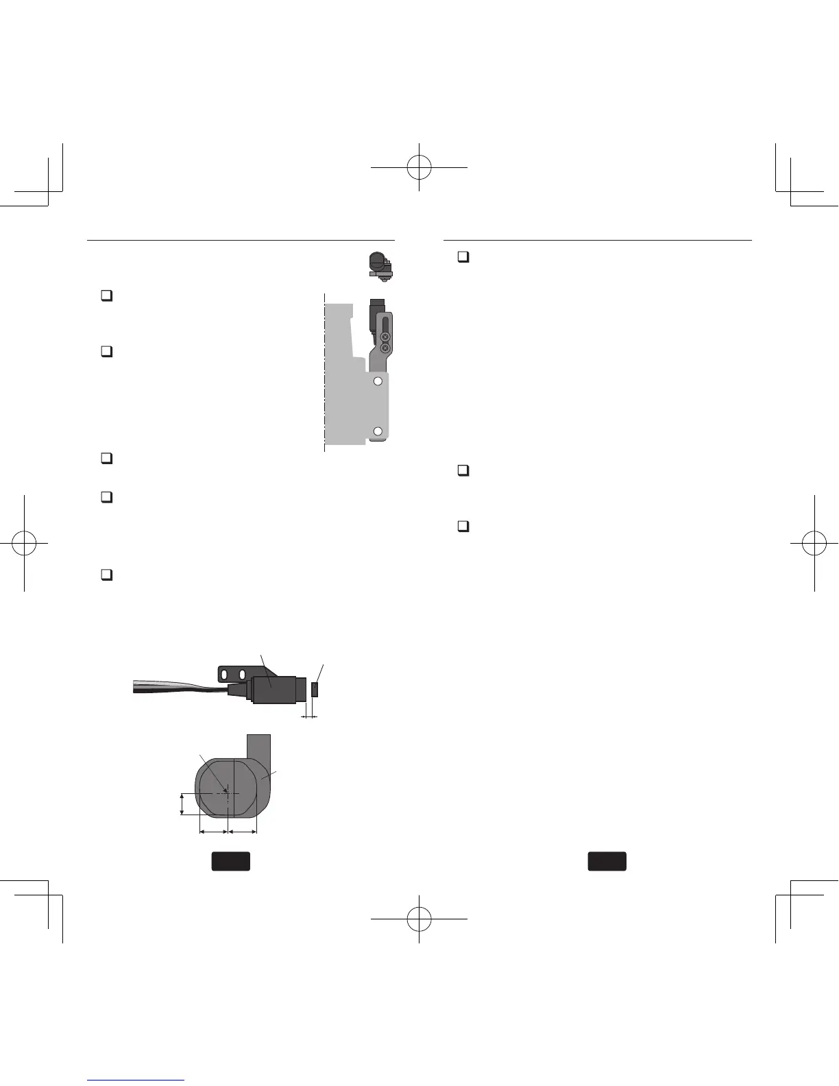
between the sensor and magnet
can be made 1 to 2mm.
Tighten the sensor stay together
with the engine mounting ange.
(Temporary assembly)
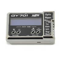
Select the mounting method so
that the sensor does not touch
the frame, or other parts of the
helicopter. Temporarily mount
the sensor and select the magnet
mounting position.
Install the sensor to the sensor
stay using the accessory screws and washers.
Tighten the sensor stay together with the en-
gine using the engine mount screw.
Sensor adjustment
Adjust the sensor position to obtain a sen-
sor output of at least 60% in the “Revolution
sensor testing” menu within the “Governor
Basic Setting” section earlier in this manual.
The center of the sensor is different from the
center of the sensor case so be careful when
mounting the sensor.
If the display is less than 60% when the
magnet is directly below the sensor, bring the
sensor closer to the magnet so that the 60%
or more is displayed. The magnet and sensor
gap criteria is approximately 1 to 2mm. If a
sensor output is not obtained even when the
sensor is brought close to the magnet, the
magnet and sensor center positions may have
changed.
Complete assembly of the sensor by securely
tightening the screws that were temporarily
tightened.
Recheck the sensor output.