Install the tail rotor servo into the mechanics
and connect the servo to the gyro. Remove
the servo arm screw from the servo. Turn the
receiver power on and allow the gyro to ini-
tialize. Enter the “Gyro Basic Setting” mode
and go to parameter (4) “Servo Limit Point
Setting”. While in the servo limits parameter
the servo will remain centered.
90°
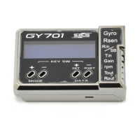
Place an appropriate servo arm onto the servo
and ensure that it is perpendicular to the tail
rotor pushrod as shown. Remove the unused
sides of the servo arm.
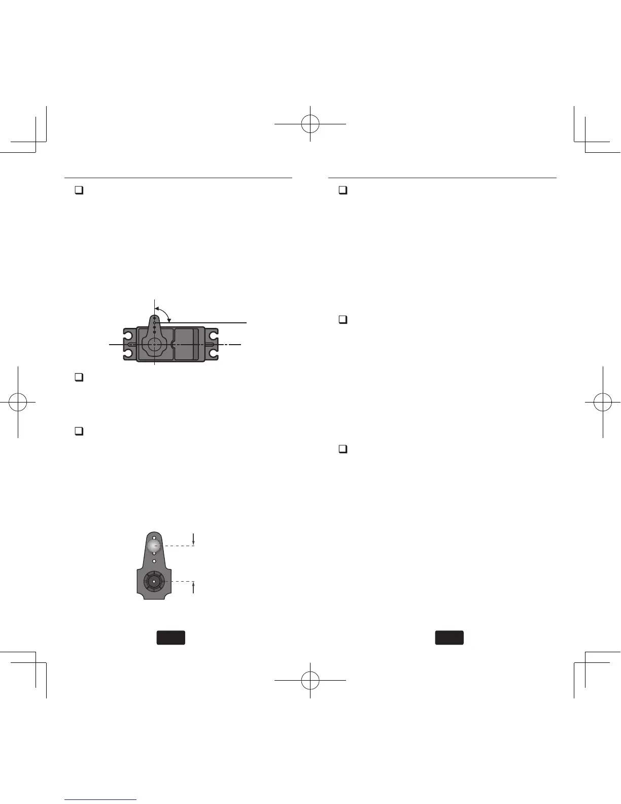
Install the control ball supplied with your he-
licopter onto the servo arm. For larger electric
models or nitro powered models we recom-
mend placing the ball 13.5mm from center.
Once the control ball has been installed place
the arm back onto the servo ensuring that it is
perpendicular to the tail rotor pushrod. Install
the servo arm screw.
13.5mm
Follow the instructions within the “Servo
Limit Point Setting” section and set the servo
limits for the tail rotor servo. Hold the tail
rotor linkage over the linkage ball to avoid
damaging the servo. Once the limits are set
you can place the linkage onto the linkage
ball. When using AVCS mode the optimum
setup is to have 0° of pitch with the tail rotor
servo centered and use all of the available
pitch range in the tail without binding.
Turn the receiver power off to exit program-
ming mode and then turn the receiver power
back on. Once the gyro has completed initial-
ization move the tail rotor stick to the right
on the transmitter and verify that right (clock-
wise rotation) tail rotor pitch is inputted to
the tail rotor blades. If left tail rotor pitch is
inputted to the tail rotor blades, then it will
be necessary to reverse the tail rotor channel
in the transmitter.
Pick the helicopter up by the main shaft
and rotate the mechanics counter-clockwise
(from the top). The gyro should compensate
by adding clockwise rotation pitch to the tail
rotor blades. If the gyro compensates by add-
ing counter-clockwise rotation pitch to the
tail rotor blades then it will be necessary to
reverse the “Gyro Direction” setting within
the gyro (refer to the “Gyro Basic Setting”
section earlier in this manual).
If you are going to y AVCS Heading Hold mode
exclusively, then the gyro setup is now complete.