EasyManuals Logo

Galil Motion Control DMC-40 0 Series Installation Manual

Galil Motion Control DMC-40 0 Series
57 pages
To Next Page IconTo Next Page
To Previous Page IconTo Previous Page
Page #17 background imageLoading...
Page #17 background image
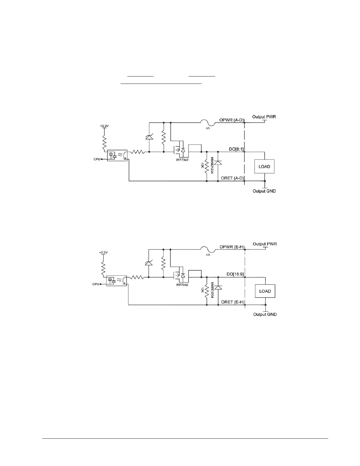
Wiring the Optoisolated Outputs
The output power supply will be connected to Output PWR (labeled OPWR) and the power supply return will be
connected to Output GND (labeled ORET). Note that the load is wired between DO and Output GND. The wiring
diagram for Bank 0 is shown in Figure 3.11 and Bank 1 in Figure 3.12. See the “I/O 44 pin HD D-sub Connectorfor
your specific ICM module in Chapter 5 Integrated Components for the correct pin-outs.
Chapter 3 Installation ▫ 14 DMC-40x0 UL Installation Manual
Figure 3.11: 500mA Sourcing wiring diagrams for Bank 0, DO[8:1]
Figure 3.12: 500mA Sourcing wiring diagram for Bank 1, DO[16:9]

Table of Contents

Other manuals for Galil Motion Control DMC-40 0 Series

Questions and Answers:

Question and Answer IconNeed help?

Do you have a question about the Galil Motion Control DMC-40 0 Series and is the answer not in the manual?

Galil Motion Control DMC-40 0 Series Specifications

General IconGeneral
BrandGalil Motion Control
ModelDMC-40 0 Series
CategoryController
LanguageEnglish

Related product manuals