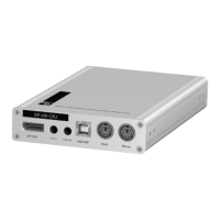
Target module »DP-HR-U-CPU-MC2-UC«
23 · Target and user modules (DP-HR-U)
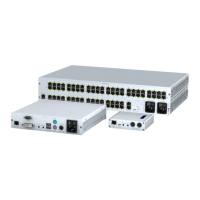
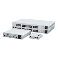
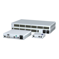
Connections to the matrix switches
Connecting the first matrix switch
Trans. 1|Channel 1: Connect this interface to a Dynamic Port (RJ45) of the first matrix
switch.
Trans. 1|Channel 2: Connect this interface to another Dynamic Port (RJ45) of the first
matrix switch.
Connecting the second matrix switch
Trans. 2|Channel 1: Connect this interface to a Dynamic Port (RJ45) of the second
matrix switch.
Trans. 2|Channel 2: Connect this interface to another Dynamic Port (RJ45) of the sec-
ond matrix switch.
Power supply
Power In: Insert the power pack’s connection cable to this interface.
Start-up
Connect the power cable to the power pack and a power socket.
The target module starts as soon as it is supplied with power. During start-up, the
channels are automatically grouped (see below).
IMPORTANT:
Connect only one of the target module’s Trans. interfaces for each
matrix switch!
NOTE:
Only use category 5e (or better) twisted pair cables to connect the devices.
ADVICE:
You can also connect the target module directly to up to two compatible
user modules.
Trans. 2 Trans. 1
Channel 1
Channel 2
Service
Power In
Power
 Loading...