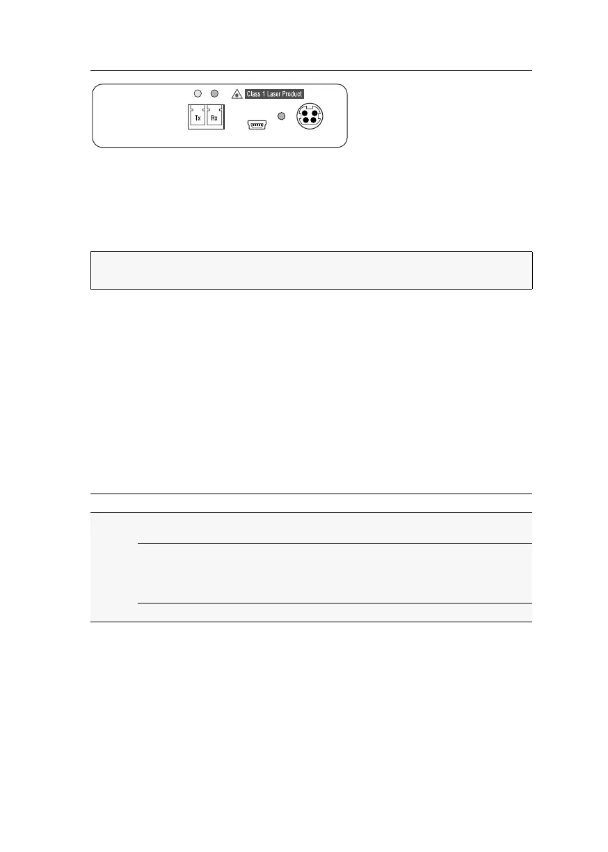
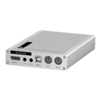
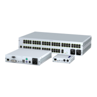
Target module »DP-HR-U-CPU-Fiber-DH«
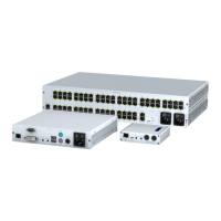
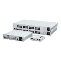
Target and user modules (DP-HR-U) · 68
Trans.|Tx: Insert the LC plug of a compatible optical fibre cable. Connect the other
end of the cable to the
Rx interface of a Dynamic Port provided at the matrix switch.
Trans.|Rx: Insert the LC plug of a compatible optical fibre cable. Connect the other
end of the cable to the
Tx interface of the same Dynamic Port provided at the matrix
switch.
Power supply
Power In: Insert the power pack’s connection cable to this interface.
Start-up
Connect the power cable to the power pack and a power socket. The target module
starts as soon as it is supplied with power.
Status displays
The Power LED on the back panel of the target module shows the status of the
external power pack:
ADVICE:
You can also connect the target module directly to a compatible user mod-
ule.
LED Status Meaning
Power Lights up
green
The external power pack is connected, and voltage of 12 Volt
is available.
Lights up
blue
The external power pack is connected, and voltage of 12 Volt
is available.
The Ident. LED to quickly identify the device has been activated
(for example, via the web application).
Off The external power pack is not (properly) connected.
Power In
Service
Power
Trans.