WLLMN WINT 2-ELEMENT
HLATER (OR EOUAL)
AWAY FROM PREVAIL ING WIND
RH7~ WITH 121 RH7W
ELWEN1.S -2 REOD
6ZC4 WATTS EACH
8 FT. (2.4M)
PLYWOOD ““F ENCEoo
@FT PLWOW FENCC
(2.4 M)
4
,m
\ _COMPKSS~
~LLMffl wlANT 2+LEMEN1
tEATER (OR EcUAL)
RH400 WITH ~ RH4~
ELEMENTS - Z SfOD
3200 wATTS EACH
+“ 4
MOTOR
/“
LJ
‘\
3 FT
4 FT.
~’(1.2M)
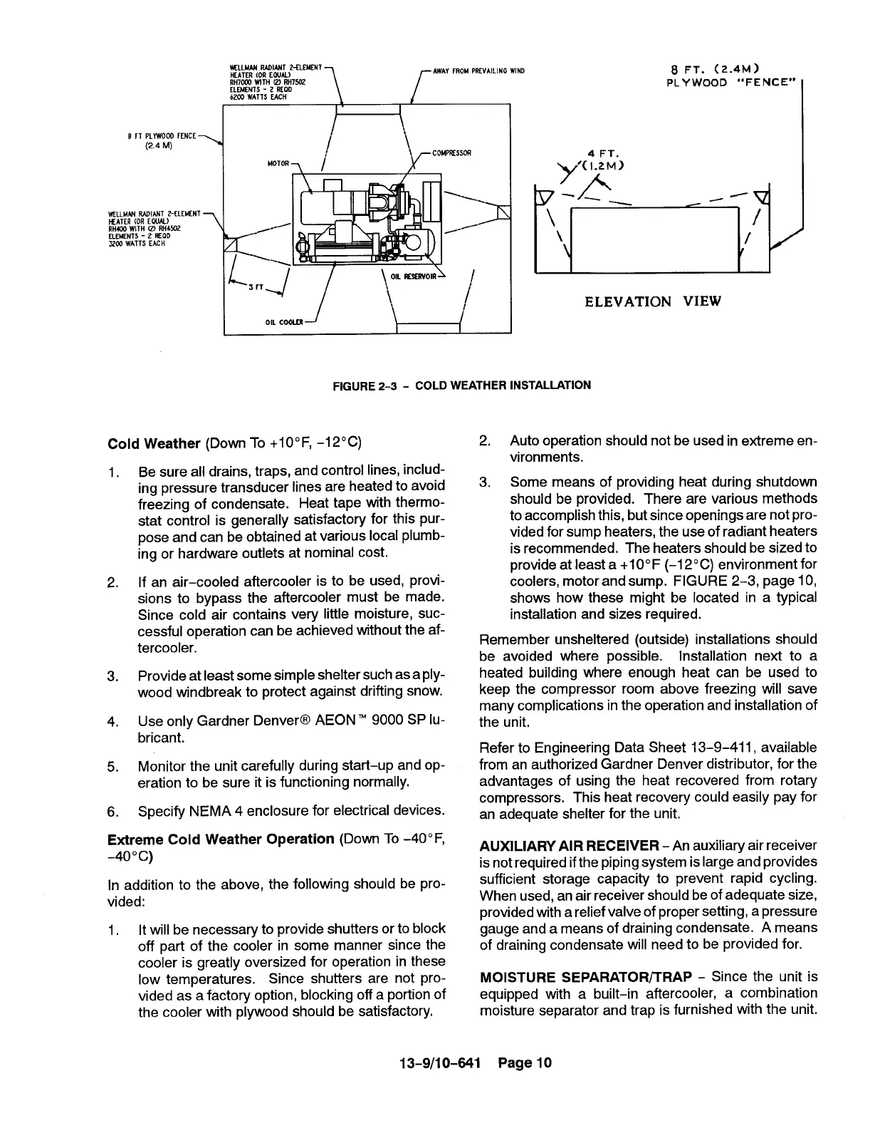
FIGURE 2-3- COLD WEATHER INSTALLATION
ELEVATION VIEW
Cold Weather (Down To +IO” F, -12°C)
1.
2.
3.
4,
5,
6.
Be sure all drains, traps, and control lines, includ-
ing pressure transducer lines are heated to avoid
freezing of condensate. Heat tape with thermo-
stat control is generally satisfactory for this pur-
pose and can be obtained at various local plumb-
ing or hardware outlets at nominal cost.
If an air-cooled aftercooler is to be used, provi-
sions to bypass the aftercooler must be made.
Since cold air contains very little moisture, suc-
cessful operation can be achieved without the af-
tercooler.
Provide at least some simple shelter such as a ply-
wood windbreak to protect against drifting snow.
Use only Gardner Denver@ AEON 9000 SP lu-
bricant.
Monitor the unit carefully during start-up and op-
eration to be sure it is functioning normally.
Specify NEMA 4 enclosure for electrical devices.
Extreme Cold Weather Operation (Down To -40° F,
-40° c)
In addition to the above, the following should be pro-
vided:
1.
It will be necessary to provide shutters or to block
off part of the cooler in some manner since the
cooler is greatly oversized for operation in these
low temperatures. Since shutters are not pro-
vided as a factory option, blocking off a portion of
the cooler with plywood should be satisfactory.
2.
Auto operation should not be used in extreme en-
vironments.
3.
Some means of providing heat during shutdown
should be provided. There are various methods
to accomplish this, but since openings are not pro-
vided for sump heaters, the use of radiant heaters
is recommended, The heaters should be sized to
provide at leasta+1O”F(-12°C) environment for
coolers, motor and sump. FIGURE 2-3, page 10,
shows how these might be located in a typical
installation and sizes required.
Remember unsheltered (outside) installations should
be avoided where possible. Installation next to a
heated building where enough heat can be used to
keep the compressor room above freezing will save
many complications in the operation and installation of
the unit.
Refer to Engineering Data Sheet 13-9-411, available
from an authorized Gardner Denver distributor, for the
advantages of using the heat recovered from rotary
compressors. This heat recovery could easily pay for
an adequate shelter for the unit.
AUXILIARY AIR RECEIVER - An auxiliary air receiver
is not required ifthe piping system is large and provides
sufficient storage capacity to prevent rapid cycling.
When used, an air receiver should be of adequate size,
provided with a relief valve of proper setting, a pressure
gauge and a means of draining condensate. A means
of draining condensate will need to be provided for.
MOISTURE SEPARATOR/TRAP - Since the unit is
equipped with a built–in aftercooler, a combination
moisture separator and trap is furnished with the unit.
13-9/10-641 Page 10