SECTION 7
COUPLING
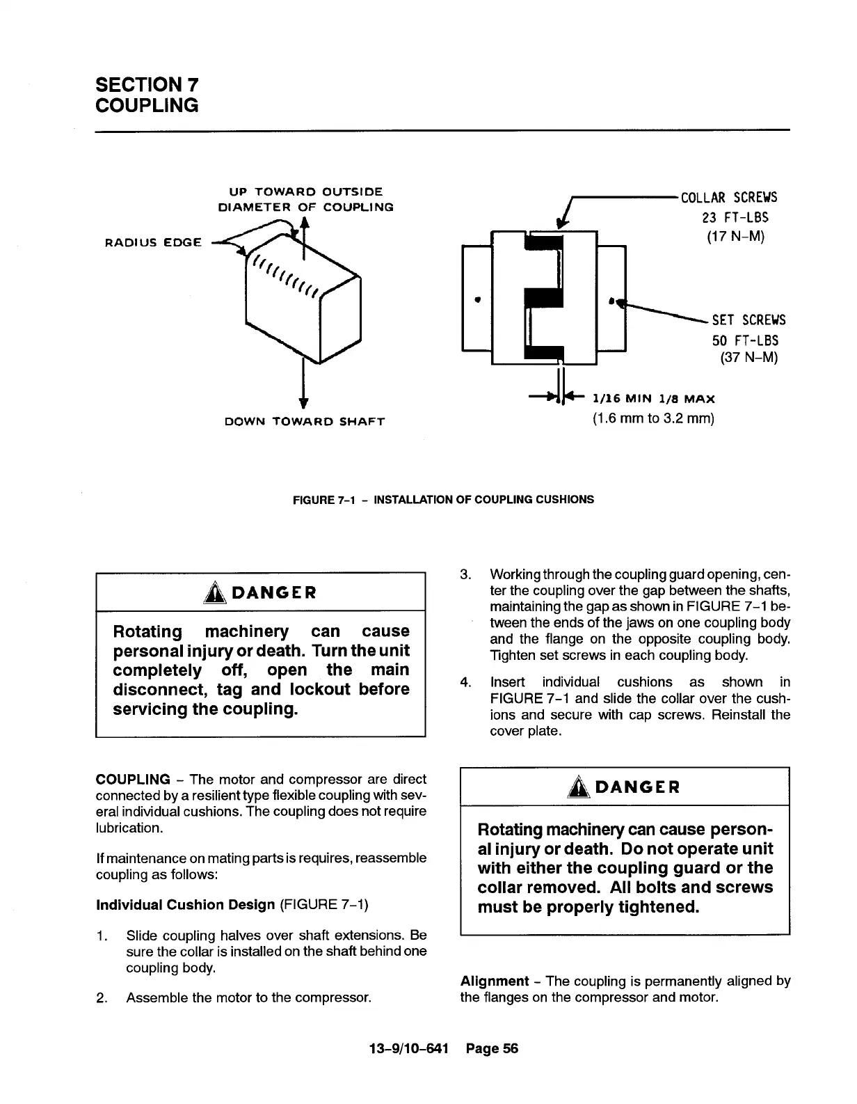
RADIUS EDGE
UP TOWARO OUTSIDE
DIAMETER OF COUPLING
*
DOWN TOWARD SHAFT
~co”” ‘CR’”
23 FT-LBS
4L
1/16 MIN 1/8 MAX
(1,6 mm to 3.2 mm)
~DANGER
Rotating
machinery
can cause
personal injury or death. Turn the unit
completely off, open the main
disconnect, tag and lockout before
servicing the coupling.
COUPLING - The motor and compressor are direct
connected by a resilient type flexible coupling with sev-
eral individual cushions. The coupling does not require
lubrication.
If maintenance on mating parts is requires, reassemble
coupling as follows:
Individual Cushion Design (FIGURE 7-1)
1. Slide coupling halves over shaft extensions. Be
sure the collar is installed on the shaft behind one
coupling body,
2.
Assemble the motor to the compressor.
13-9/10-641
(17 N-M)
L
8
SET SCREUS
-1
50 FT-LBS
(37 N-M)
FIGURE 7-1 - INSTALLATION OF COUPLING CUSHIONS
3.
4.
Working through the coupling guard opening, cen-
ter the coupling over the gap between the shafts,
maintaining the gap as shown in FIGURE 7-1 be-
tween the ends of the jaws on one coupling body
and the flange on the opposite coupling body.
Tighten set screws in each coupling body.
Insert individual cushions as shown in
FIGURE 7-1 and slide the collar over the cush-
ions and secure with cap screws. Reinstall the
cover plate.
/~\ DANGER
Rotating machinery can cause person-
al injury or death. Do not operate unit
with either the coupling guard or the
collar removed. All bolts and screws
must be properly tightened.
Alignment - The coupling is permanently
the flanges on the compressor and motor.
Page 56
aligned by