SECTION 4
CONTROLS & INSTRUMENTATION
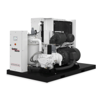
GENERAL DESCRIPTION - The Gardner Denver
rotary screw compressor is prewired with all controls,
motor, and starter for the voltage and horsepower at
the time of ordering. It is necessary only to connect the
compressor unit to the correct power supply, to the
shop air line, and to the appropriate shop water line, if
the compressor is water-cooled. A standard compres-
sor unit consists of the compressor, oil reservoir, oil
cooling system and filters, motor type as specified,
NEMA 12 starter /control box, and control components
as described below.
This compressor unit features the “AUTO SENTRY-
ES controller, which integrates all the control functions
under microprocessor control. Its functions include
safety and shutdown, compressor regulation, operator
control, and advisory / maintenance indicators. The
keypad and display provide the operator with a logical
and easily operated control of the compressor and in-
dication of its condition.
AUTO SENTRY'-ES OPERATION
Operation of the “Auto Sentry-ES’ is dependent on
selection of an operating mode (described below) from
the controller keypad.
Before starting, press the
[STOP/RESET] key to place the controller into its
READY state (as indicated on the display). Compres-
sor operation may then be started by pressing an oper-
ating mode key. Once operating, the mode may be
changed at any time by pressing a key, and the se-
lected mode will be displayed in the lower right corner
of the message window. Press the [STOP/RESET] key
at anytime to stop the compressor under normal condi-
tions,
An optional control maybe wired into the “Auto Sentry-
ES controller to interrupt and restart the unit based on
controls by others. When stopped by these controls,
the display indicates “REMOTE STOP”.
~WARNING
Automatic restarting or electrical
shock can cause injury or death.
Open, tag and lockout main discon-
nect and any other circuits before
servicing the unit.
In any mode, the compressor will start only if reservoir
pressure is below5 psig. The display will indicate ifthe
13-9/1
0-641
control is waiting for a reservoir blowdown, along with
the remaining pressure, The controls also delay initial
loading of the compressor until a startup delay has
been completed.
Constant Run Mode Operation - Use this mode in
applications where there are no long periods of un-
loaded operation, or for minimum response time to sud-
den demands. The compressor unit will start and run
continuously, using its modulation controls to match
delivery to demand.
As demand falls below the compressor capacity, the
pressure will rise to the setpoint of the control. When
the pressure reaches the setpoint, the “Auto Sentry-
ES controller operates the solenoid valves IVO and
IVC to pass pressure to the inlet valve piston, and the
inlet valve will close enough to match itto the air system
demand.
As demand increases, the controller will modulate the
inlet valve by relieving pressure with the solenoid
valves IVO and IVC as required to match delivery to de-
mand. Once the compressor has been first loaded, it
will maintain pressure within a few psi of the setpoint
pressure. This is true for any demand within its rated
capacity.
On units equipped with turn valve control, further in-
crease in demand will cause the inlet valve to be held
fully open. Turn valve solenoid valves TVC and TVO
control compressor delivery. The controller automati-
cally controls the two methods of modulation to provide
the most efficient means of delivery to match the de-
mand of the system under all conditions.
Low Demand Mode Operation - The low demand
mode reduces power consumption by relieving pres-
sure in the reservoir during unloaded operation. Use
this mode where there is moderate air storage and
there are unloaded periods during the day, but frequent
motor starting and stopping is undesirable. During peri-
ods of moderate to high demands, this mode is identi-
cal to the constant-run mode described above.
During Iowdemand periods, the controller will open the
blowdown valve and fully close the inlet valve to mini-
mize the motor load. A timer is reset when this occurs.
While in this state, the plant air system supplies control
air pressure (as well as any plant loads). When the sys-
tem air pressure drops to the reset pressure due to in-
creased demand, the blowdown valve recloses and the
controls resume their normal modulation sequence.
Subsequent blowdown periods are not allowed until the
timer has completed its cycle. This cycle eliminates
frequent blowdowns during moderate loads, and the
Page 18