SECTION 1
GENERAL INFORMATION
v
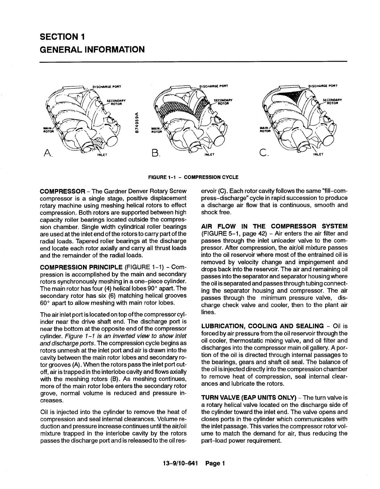
FIGURE 1-1 - COMPRESSION CYCLE
COMPRESSOR - The Gardner Denver Rotary Screw
compressor is a single stage, positive displacement
rotary machine using meshing helical rotors to effect
compression. Both rotors are supported between high
capacity roller bearings located outside the compres-
sion chamber. Single width cylindrical roller bearings
are used at the inlet end of the rotors to carry part of the
radial loads. Tapered roller bearings at the discharge
end locate each rotor axially and carry all thrust loads
and the remainder of the radial loads.
COMPRESSION PRINCIPLE (FIGURE l-l) - Com-
pression is accomplished by the main and secondaty
rotors synchronously meshing in a one-piece cylinder.
The main rotor has four (4) helical lobes 90° apart. The
secondary rotor has six (6) matching helical grooves
60° apart to allow meshing with main rotor lobes.
The air inlet port is located on top ofthe compressor cyl-
inder near the drive shaft end. The discharge port is
near the bottom at the opposite end of the compressor
cylinder. Figure 1-1 is an invetted view to show inlet
and discharge ports. The compression cycle begins as
rotors unmesh at the inlet port and air is drawn into the
cavity between the main rotor lobes and secondary ro-
tor grooves (A). When the rotors pass the inlet port cut-
off, air is trapped inthe interlobe cavity and flows axially
with the meshing rotors (B). As meshing continues,
more of the main rotor lobe enters the secondary rotor
grove, normal volume is reduced and pressure in-
creases.
Oil is injected into the cylinder to remove the heat of
compression and seal internal clearances. Volume re-
duction and pressure increase continues until the air/oil
mixture trapped in the interlobe cavity by the rotors
passes the discharge port and is released to the oil res-
13-9/1 0-641
v
ervoir (C). Each rotor cavity follows the same “fill–com-
press-discharge” cycle in rapid succession to produce
a discharge air flow that is continuous, smooth and
shock free.
AIR FLOW IN THE COMPRESSOR SYSTEM
(FIGURE 5-1, page 42) - Air enters the air filter and
passes through the inlet unloader valve to the com-
pressor. After compression, the air/oii mixture passes
into the oil reservoir where most of the entrained oil is
removed by velocity change and impingement and
drops back into the reservoir. The air and remaining oil
passes into the separator and separator housing where
the oil isseparated and passes through tubing connect-
ing the separator housing and compressor. The air
passes through the minimum pressure valve, dis-
charge check valve and cooler, then to the plant air
lines.
LUBRICATION, COOLING AND SEALING - Oil is
forced by air pressure from the oil reservoir through the
oil cooler, thermostatic mixing valve, and oil filter and
discharges into the compressor main oil gallery. A por-
tion of the oil is directed through internal passages to
the bearings, gears and shaft oil seal. The balance of
the oilis injected directly into the compression chamber
to remove heat of compression, seal internal clear-
ances and lubricate the rotors,
TURN VALVE (EAP UNITS ONLY) - The turn valve is
a rotary helical valve located on the discharge side of
the cylinder toward the inlet end, The valve opens and
closes ports in the cylinder which communicates with
the inlet passage. This varies the compressor rotor vol-
ume to match the demand for air, thus reducing the
part-load power requirement.
Page 1