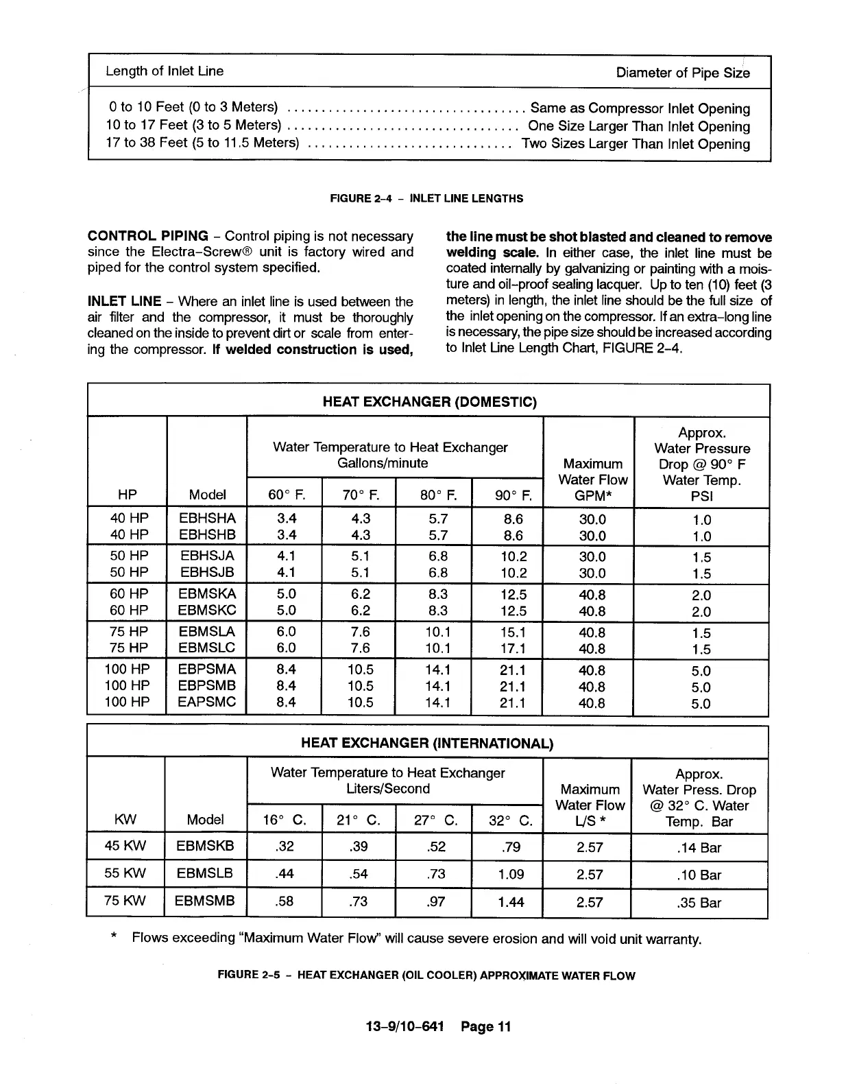
Length of Inlet Line
Diameter of Pipe Size
OtolOFeet (Oto3 Meters) . . . . . . . . . . . . . . . . . . . . . . . . . . . . . . . . . . .
Same as Compressor Inlet Opening
10 to 17 Feet (3 t05 Meters) . . . . . . . . . . . . . . . . . . . . . . . . . . . . . . . . . . One Size LargerThan Inlet Opening
17 t038Feet (5 toll,5 Meters). . . . . . . . . . . . . . . . . . . . . . . . . . . . . .
Two Sizes Larger Than Inlet Opening
FIGURE 2-4 - INLET LINE LENGTHS
CONTROL PIPING - Control piping is not necessary
the line must be shot blasted and cleaned to remove
since the Electra–Screw@ unit is factory wired and
welding scale. In either case, the inlet line must be
piped for the control system specified.
coated internally by galvanizing or painting with a mois-
ture and oil-proof sealing lacquer, Up to ten (1O)feet (3
INLET LINE - Where an inlet line is used between the
meters) in length, the inlet line should be the full size of
air filter and the compressor, it must be thoroughly
the inlet opening on the compressor. If an extra-long line
cleaned on the inside to prevent dirtor scale from enter-
isnecessary, the pipe size should be increased according
ing the compressor. If welded construction is used,
to Inlet Line Length Chart, FIGURE 2-4,
HP
40 HP
40 HP
50 HP
50 HP
60 HP
60 HP
75 HP
75 HP
100 HP
100 HP
100 HP
Model
EBHSHA
EBHSHB
EBHSJA
EBHSJB
EBMSKA
EBMSKC
EBMSLA
EBMSLC
EBPSMA
EBPSMB
EAPSMC
HEAT EXCHANGER (DOMESTIC)
Water Temperature to Heat Exchanger
3.4 I 4.3 I 5.7 I 8.6 I 30.0
3.4
I
4.3
5.7
I
8.6
I
30.0
4.1
I
5,1
I
6.8
I
10.2
I
30.0
4.1 5,1
6.8
10.2 30.0
,
5.0
I
6.2
I
8.3
I
12.5
I
40.8
5.0 6.2
8.3
12.5 40.8
6,0 7,6
10.1
15.1 40.8
6.0 7,6
10,1
17.1
40.8
8.4 10.5
14.1
21.1 40.8
8.4 10.5
14.1
21.1 40.8
8,4 10,5
14.1
21.1 40,8
Approx.
Water Pressure
Drop @ 90° F
Water Temp.
Psl
1.0
1.0
1,5
1.5
2.0
2.0
1.5
1.5
5.0
5.0
5.0
Kw
45 Kw
55 Kw
75 Kw
HEAT EXCHANGER (INTERNATIONAL)
Water Temperature to Heat Exchanger
Approx.
Liters/Second Maximum
Water Press. Drop
Water Flow
@ 32° C. Water
Model 16° C. 21° c. 27° C,
32° C. L/s * Temp. Bar
EBMSKB
.32 .39
.52
.79 2,57 .14 Bar
EBMSLB .44 .54
.73
1.09 2.57 .10 Bar
EBMSMB
.58
.73 .97
1.44 2.57 .35 Bar
* Flows exceeding “Maximum Water FIow" will cause severe erosion and will void unit warranty.
FIGURE 2-5- HEAT EXCHANGER (OIL COOLER) APPROXIMATE WATER FLOW
13-9/1 0-641 Page 11