PUR
MINIMUM
PRESSURE
)
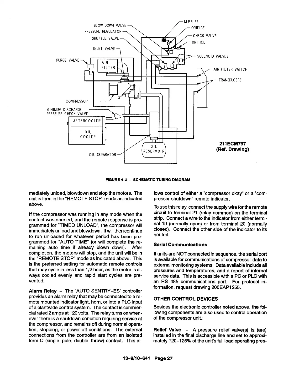
FIGURE 4-2- SCHEMATIC TUBING DIAGRAM
mediately unload, blowdown and stop the motors. The
unit is then in the “REMOTE STOP mode as indicated
above.
If the compressor was running in any mode when the
contact was opened, and the remote response is pro-
grammed for “TIMED UNLOAD, the compressor will
immediately unload and blowdown. It willthen continue
to run unloaded for whatever period has been pro-
grammed for “AUTO TIME (or will complete the re-
maining auto time if already blown down). After
completion, the motors will stop, and the unit will be in
the “REMOTE STOP mode as indicated above, This
is the preferred setting for automatic remote controls
that may cycle in less than 1/2 hour, as the motor is al-
ways cooled evenly and rapid start cycles are pre-
vented.
Alarm Relay - The “AUTO SENTRY-ES controller
provides an alarm relay that maybe connected to a re-
mote mounted indicator light, horn, or into a PLC input
of a plantwide control system. The contact is commer-
cial rated 2 amps at 120 volts. The relay turns on when-
ever there is a shutdown condition requiring service at
the compressor, and remains off during normal opera-
tion, stopping, or power off conditions. The external
connections from the controller are from an isolated
form C (single-pole, double-throw) contact. This al-
13-9/10-641
lows control of either a “compressor okay” or a “com-
pressor shutdown” remote indicator,
To use this relay, connect the supply wire for the remote
circuit to terminal 21 (relay common) on the terminal
strip. Connect a wire to the indicator from either termi-
nal 19 (normally open) or from terminal 20 (normally
closed). Connect the other side of the indicator to its
neutral.
Serial Communications
If units are NOT connected in sequence, the serial port
is available for communications of compressor data to
external monitoring systems. Data available include all
pressures and temperatures, and a report of internat
service data. This is accessible with a PC or PLC with
an RS-485 communications port. For protocol in-
formation, request drawing 200 EAP1255.
OTHER CONTROL DEVICES
Besides the electronic controller noted above, the fol-
lowing components are also used to control operation
of the compressor unit.:
Relief Valve - A pressure relief valve(s) is (are)
installed in the final discharge line and set to approxi-
mately 120-1 25% of the unit’s full load operating pres-
Page 27