OIL SEPARATOR
COVER
PLATE
OIL SEPARATOR—
HOMING
OR
NE
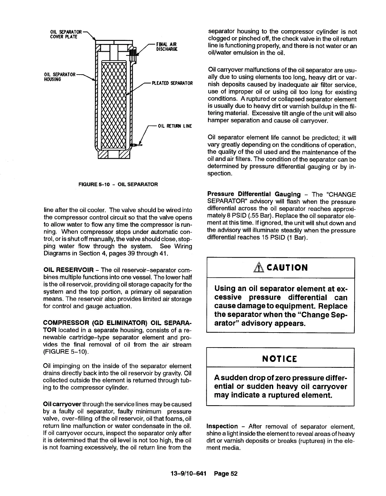
FIGURE 5-10- OIL SEPARATOR
line after the oil cooler. The valve should be wired into
the compressor control circuit so that the
valve opens
to allow water to flow any time the compressor is run-
ning. When compressor stops under automatic con-
trol, or isshut off manually, the valve should close, stop-
ping water flow through the system. See Wiring
Diagrams in Section 4, pages 39 through 41.
OIL RESERVOIR - The oil reservoir-separator com-
bines multiple functions into one vessel. The lower half
isthe oil reservoir, providing oil storage capacity for the
system and the top portion, a primary oil separation
means. The reservoir also provides limited air storage
for control and gauge actuation.
COMPRESSOR (GD ELIMINATOR) OIL SEPARA-
TOR located in a separate housing, consists of a re-
newable cartridge-type separator element and pro-
vides the final removal of oil from the air stream
(FIGURE 5-10).
Oil
impinging on the inside of the separator element
drains directly back into the oil reservoir by gravity, Oil
collected outside the element is returned through tub-
ing to the compressor cylinder.
Oil carryover through the service lines may be caused
by a faulty oil separator, faulty minimum pressure
valve, over-filling of the oil reservoir, oil that foams, oil
return line malfunction or water condensate in the oil,
If oil carryover occurs, inspect the separator only after
it is determined that the oil level is not too high, the oil
is not foaming excessively, the oil return line from the
separator housing to the compressor cylinder is not
clogged or pinched off, the check valve in the oil return
line is functioning properly, and there is not water or an
oil/water emulsion in the oil.
Oil carryover malfunctions of the oil separator are usu-
ally due to using elements too long, heavy dirt or var-
nish deposits caused by inadequate air filter service,
use of improper oil or using oil too long for existing
conditions. A ruptured or collapsed separator element
is usually due to heavy dirt or varnish buildup in the fil-
tering material. Excessive tilt angle of the unit will also
hamper separation and cause oil carryover.
Oil separator element life cannot be predicted; it will
vary greatly depending on the conditions of operation,
the quality of the oil used and the maintenance of the
oil and air filters. The condition of the separator can be
determined by pressure differential gauging or by in-
spection.
Pressure Differential Gauging - The “CHANGE
SEPARATOR” advisory will flash when the pressure
differential across the oil separator reaches approxi-
mately 8 PSID (.55 Bar). Replace the oil separator ele-
ment at this time. If ignored, the unit will shut down and
the advisorv will illuminate steadily when the pressure
differential reaches 15 PSID (1 Bar).
~CAUTiON
Using an oil separator element at ex-
cessive pressure differential can
cause damage to equipment. Replace
the separator when the “Change Sep-
arator” advisory appears.
NOTICE
A sudden drop of zero pressure differ-
ential or sudden heavy oil carryover
may indicate a ruptured element.
Inspection - After removal of separator element,
shine alight inside the element to reveal areas of heavy
dirt or varnish deposits or breaks (ruptures) in the ele-
ment media.
13-9/10-841 Page 52
 Loading...