FIGURE 4-6- SHUITLE VALVE
Shuttle Valve (FIGURE 4-6) - Also known as a
double check valve, the shuttle valve is a device which
will take two (2) supply signals and allow the one with
the highest pressure to pass through. The shuttle valve
is used to provide control air pressure from either the
reservoir or plant air system, as required during differ-
ent operating conditions.
Purge Air Valve - The purge valve is a normally closed
two-way air actuated valve that admits purge air from
4
the final discharge manifold to the compressor to coun-
teract the oil knock that occurs in oil-flooded rotary
screw compressors when they are completely un-
loaded with pressure in the oil reservoir. This valve is
controlled by the same control pressure which controls
the inlet valve.
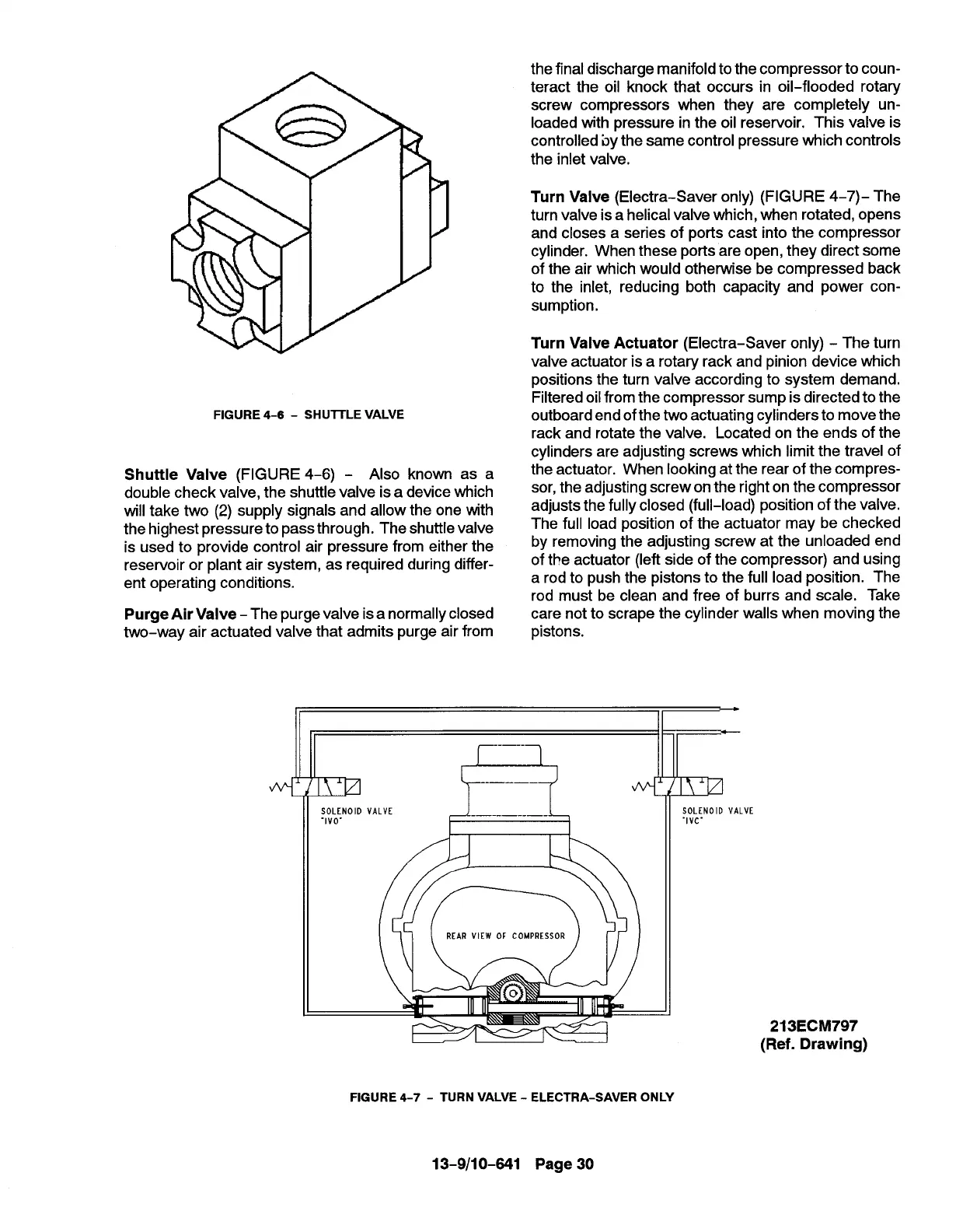
Turn Valve (Electra-Saver only) (FIGURE 4-7)- The
turn valve is a helical valve which, when rotated, opens
and closes a series of ports cast into the compressor
cylinder. When these ports are open, they direct some
of the air which would otherwise be compressed back
to the inlet, reducing both capacity and power con-
sumption.
Turn Valve Actuator (Electra-Saver only) - The turn
valve actuator is a rotary rack and pinion device which
positions the turn valve according to system demand.
Filtered oilfrom the compressor sump is directed to the
outboard end ofthe two actuating cylinders to move the
rack and rotate the valve. Located on the ends of the
cylinders are adjusting screws which limit the travel of
the actuator. When looking at the rear of the compres-
sor, the adjusting screw on the right on the compressor
adjusts the fully closed (full-load) position of the valve.
The full load position of the actuator may be checked
by removing the adjusting screw at the unloaded end
of the actuator (left side of the compressor) and using
a rod to push the pistons to the full load position. The
rod must be clean and free of burrs and scale. Take
care not to scrape the cylinder walls when moving the
pistons.
J I
I I I
I I
SOLENOID VALVE
-lvc-
213ECM797
(Ref. Drawing)
FIGURE 4-7- TURN VALVE - ELECTRA-SAVER ONLY
13-9/10-641 Page 30