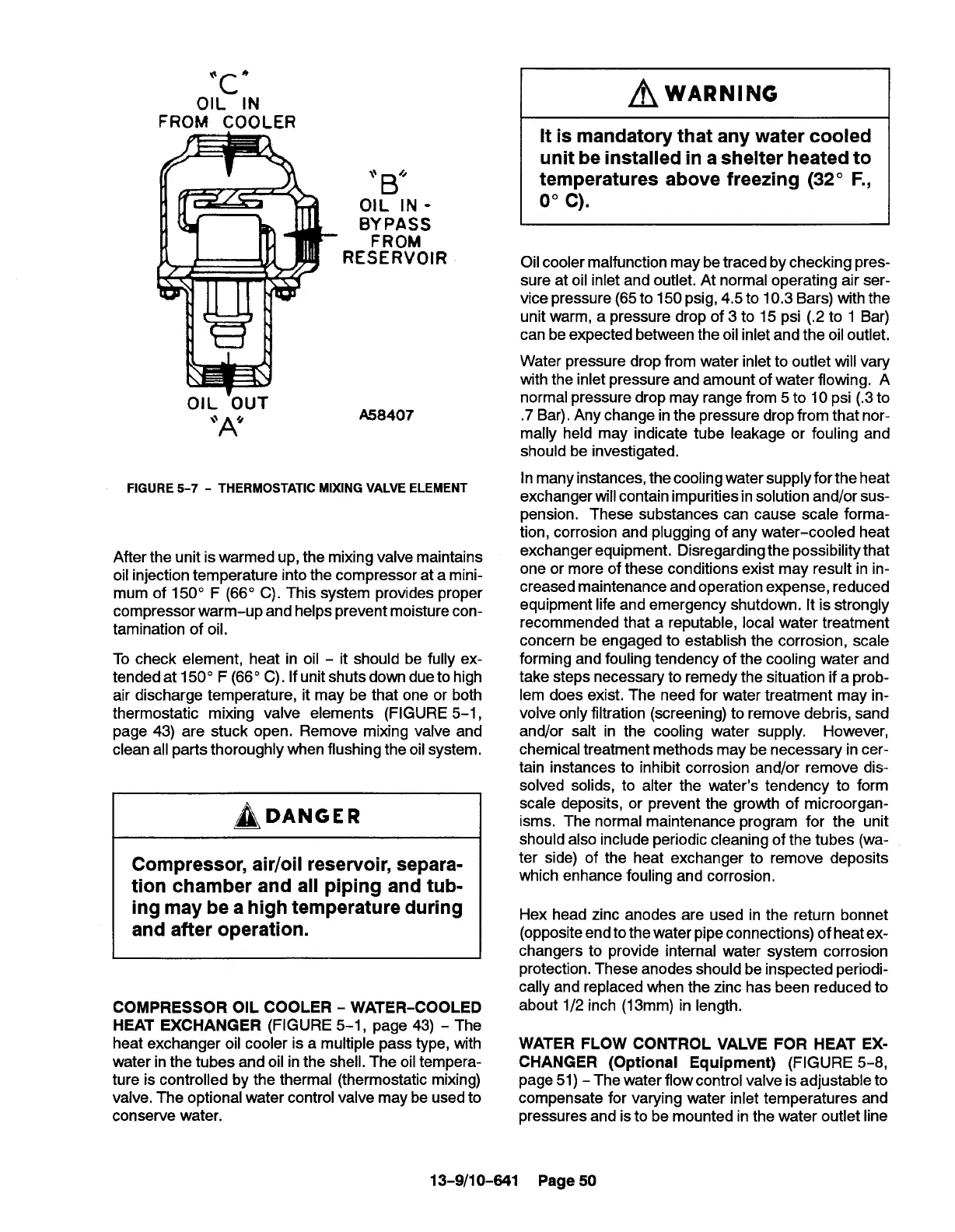
OIL”lN
~wARNiNG
FROM COOLER
“B’
OIL lN -
B;:~~S
RESERVOIR
OIL ‘OUT
“A’
A58407
FIGURE 5-7 - THERMOSTATIC MIXING VALVE ELEMENT
After the unit is warmed up, the mixing valve maintains
oil injection temperature into the compressor at a mini-
mum of 150° F (66° C). This system provides proper
compressor warm-up and helps prevent moisture con-
tamination of oil.
To check element, heat in oil - it should be fully ex-
tended at 150° F (66° C). If unit shuts down due to high
air discharge temperature, it may be that one or both
thermostatic mixing valve elements (FIGURE 5-1,
page 43) are stuck open. Remove mixing valve and
clean all parts thoroughly when flushing the oil system.
~DANGER
Compressor, air/oil reservoir, separa-
tion chamber and all piping and tub-
ing may be a high temperature during
and after operation.
COMPRESSOR OIL COOLER - WATER-COOLED
HEAT EXCHANGER (FIGURE 5-1, page 43) - The
heat exchanger oil cooler is a multiple pass type, with
water in the tubes and oil in the shell. The oil tempera-
ture is controlled by the thermal (thermostatic mixing)
valve. The optional water control valve may be used to
conserve water.
It is mandatory that any water cooled
unit be installed in a shelter heated to
temperatures above freezing (32° F.,
0°c).
Oil cooler malfunction may be traced by checking pres-
sure at oil inlet and outlet. At normal operating air ser-
vice pressure (65 to 150 psig, 4,5 to 10.3 Bars) with the
unit warm, a pressure drop of 3 to 15 psi (.2 to 1 Bar)
can be expected between the oil inlet and the oil outlet.
Water pressure drop from water inlet to outlet will vary
with the inlet pressure and amount of water flowing. A
normal pressure drop may range from 5 to 10 psi (.3 to
.7 Bar). Any change in the pressure drop from that nor-
mally held may indicate tube leakage or fouling and
should be investigated.
In many instances, the cooling water supply for the heat
exchanger will contain impurities in solution and/or sus-
pension. These substances can cause scale forma-
tion, corrosion and plugging of any water-cooled heat
exchanger equipment. Disregarding the possibility that
one or more of these conditions exist may result in in-
creased maintenance and operation expense, reduced
equipment life and emergency shutdown. It is strongly
recommended that a reputable, local water treatment
concern be engaged to establish the corrosion, scale
forming and fouling tendency of the cooling water and
take steps necessary to remedy the situation if a prob-
lem does exist. The need for water treatment may in-
volve only filtration (screening) to remove debris, sand
and/or salt in the cooling water supply. However,
chemical treatment methods may be necessary in cer-
tain instances to inhibit corrosion and/or remove dis-
solved solids, to alter the water’s tendency to form
scale deposits, or prevent the growth of microorgan-
isms, The normal maintenance program for the unit
should also include periodic cleaning of the tubes (wa-
ter side) of the heat exchanger to remove deposits
which enhance fouling and corrosion,
Hex head zinc anodes are used in the return bonnet
(opposite endtothe water pipe connections) of heat ex-
changers to provide internal water system corrosion
protection. These anodes should be inspected periodi-
cally and replaced when the zinc has been reduced to
about 1/2 inch (13mm) in length.
WATER FLOW CONTROL VALVE FOR HEAT EX-
CHANGER (Optional Equipment) (FIGURE 5-8,
page 51) - The water flow control valve is adjustable to
compensate for varying water inlet temperatures and
pressures and is to be mounted in the water outlet line
13-9/10-641 Page 50