Page 22
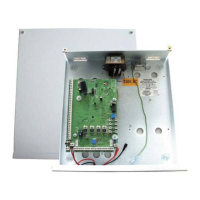
Wiring Connections
Output Connections
The output connections for the GardTec 872 are situated along the bottom edge of the
main PCB in the master control panel.
Warning:-
It should be noted that the total output current available for the GardTec 872 is 1
Amp. Any attempt to draw a total current greater than this could result in serious
damage to the control panel that is not covered by the manufacturers warranty.
Below is a description of each terminal. The order given is the same as the terminal
order on the PCB looking from left to right.
Output Terminal Descriptions
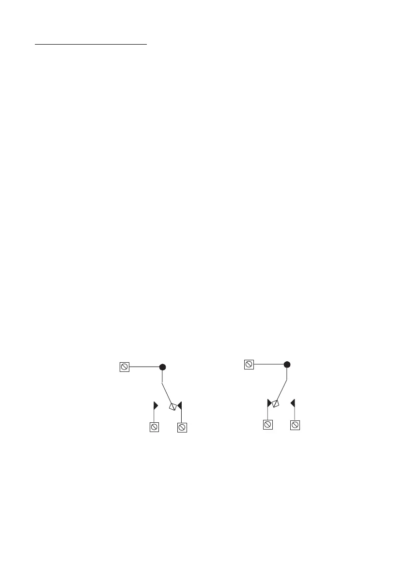
RELAY COMM
A 24V 1Amp *
1
changeover relay is provided on the GardTec 872 PCB. This relay is
fully programmable (refer to Programmable Options Description). The relay contacts
are voltage free. This terminal is the common connection (see Fig. 13).
N/O
Normally Open connection for onboard relay (see Fig. 13).
N/C
Normally Closed connection for onboard relay (see Fig. 13).
Fig. 13 Onboard Relay Operation
*
1
No attempt should be made to exceed the stated current and the 1 Amp
maximum current draw from the control panel must be taken into consideration.