Page 45
GardTec 872
Wiring Connections
ID Expanders
The GardTec ID Expander card allows thirty detectors to be fitted on a four wire run
using industry standard ID biscuits or ID compatible devices. Two ID expander cards
can be fitted to the control panel. The control panel zones may still be programmed as
'Normal (4 wire)', 'Two Wire' or 'Two Wire EOL. When used to full capacity this allows
the GardTec 872 to have up to 16 control panel zones plus 60 ID zones. Radio
Expanders cannot be used if ID Expansion has been chosen.
Each ID expander may be wired back to the control panel with standard alarm four
core cable.
Wiring Configurations
Several configurations may be used for wiring the ID expanders to the control panel,
these are:-
One ID Expander onboard the control panel PCB.
The expander is simply plugged across the molex pins marked as EXP1 and EXP2
One ID Expander remote from the control panel PCB.
This will require a Remote Expander cable (Part No. 01-094). This cable is plugged on
to EXP1 with the Red wire to pin 1 and is wired to the ID Expander.
One ID Expander onboard the control panel PCB and one ID Expander remote
from the PCB.
The first module is plugged across the molex pins on the control panel PCB marked as
EXP1 and EXP2. The second module is then wired to the first.
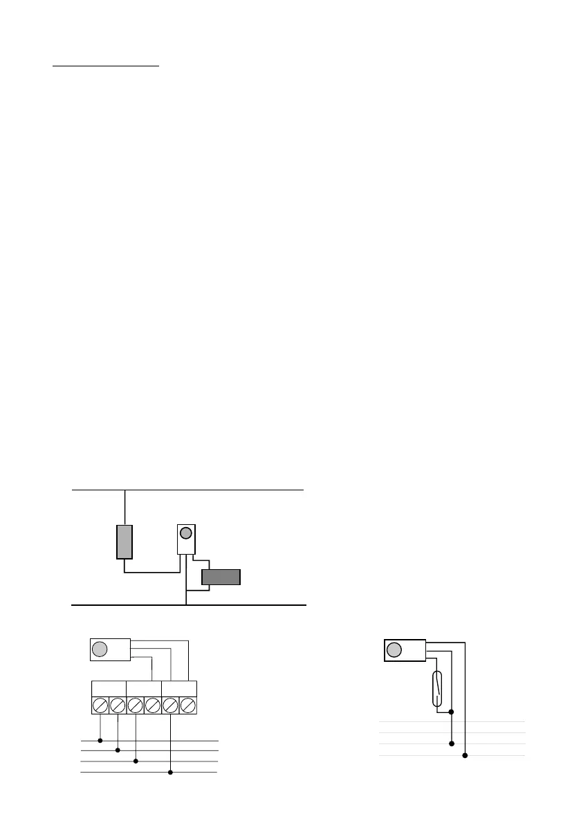
Fig 32 ID Biscuit Wiring Diagram Full wiring details are supplied with the ID
Expander Board Zone No’s 21 - 50 are on ID card 1 (SAD1) Zone No’s 51 - 80 are on
ID card 2 (SAD2)
Fig33 Detector Using Wired ID Biscuit Fig34 Wired ID Biscuit for Contact/PA