Part # 4523133 Rev 4 (08/04/09)Page 12
INSTALLATION continued
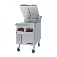
Photo C
Accessory Kit – Electrical Supply Lines:
The accessory kit also contains electric power cord and
plug and has a stain relief suited for each unit. See Plug
Conguration in SPECIFICATIONS and Photo D
InstallationofCordAndPlugWithStrainRelief:
1. Remove the left grease bucket support attached by two
metal screws and the stainless steel left side body panel
attached by ve metal screws.
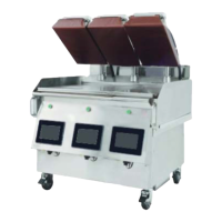
2. Removethecord&plugandstrainreliefassemblyfrom
the accessory kit. Refer to photo D.
Photo D
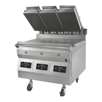
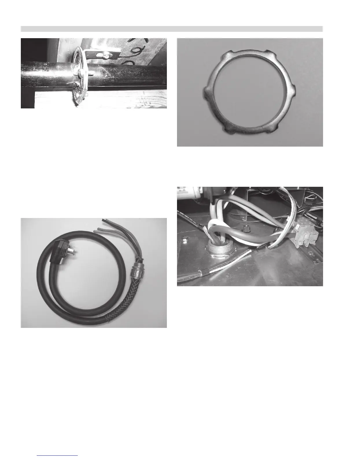
3. Remove the locknut from at the end of the cord. Refer to
photo E.
Photo E
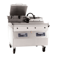
4. Insert loose wires and strain relief cord end through the
hole at the bottom of the unit Refer to photo F and secure
with locknut. Refer to photo E.
Photo F
5. Attached wire ends to terminal block as shown in next
section and referenced in wiring diagrams at back of this
manual.
6. Reinstall the side panel and grease bucket support with
metal screws. The external electrical connection should
appear as in photo G.

 Loading...