Part # 4523133 Rev 4 (08/04/09) Page 13
INSTALLATION continued
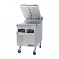
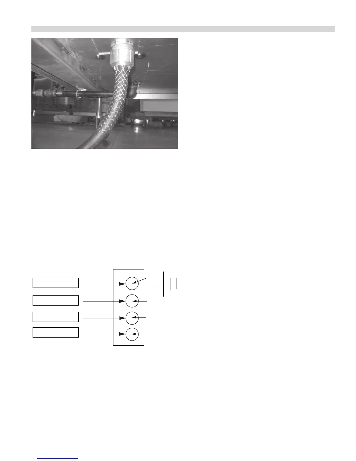
Photo G
Electrical Connection
Terminal Block Connection
All electrically operated appliances must be electrically
grounded in accordance with local codes; or in the absence
of local codes, with the latest edition of National Wiring
Regulations. A wiring diagram is located behind the rear
panel of the grill. See rating plate in rear of grill, or lower front
panel for proper voltages.
Note: see diagram below for connections to terminal block.
Green-Ground
White - Z
Black - Y
Red - X
Cord and Plug
Block of Grill
G
Z
Y
X
Grease Bucket:
The griddle is supplied with two stainless steel side grease
buckets that must be installed before the unit is used. Each
bucket slides into position along stainless steel supports.
Appliances Equipped with Casters:
1. The installation shall be made with a connector that
complies with the Standard for Connectors for Moveable
Gas Appliances, ANSI Z21.69 or latest edition, addenda
Z21.69a-1989, and a quick-disconnect device that
complies with the Standard for Quick Disconnects for Use
with Gas Fuel. ANSI Z21.41 or latest edition.
2. The front casters on the appliance are equipped with
brakes to limit the movement of the appliance without
placing any strain on the connector or quick-disconnect
device or its associated piping.
3. Please be aware; required restraint is attached to a
bracket (which is located on the rear caster closest to the
gas connection), and if disconnection of the restraint
is necessary; be sure to reconnect the device after the
appliance has been returned to its original position.
Ventilation and Clearance:
One of the most important considerations for ecient grill
operation is proper ventilation and air supply. Insure the
grill is installed so the products of combustion are removed
eciently and the ventilation system does not produce
drafts that interfere with proper burner operation.
Proper operation of exhaust fans (speed, rotation and
adjustment) is essential. In addition to the exhaust system
the make-up air system, (HVAC), for the kitchen is the
air supply for the combustion air for the burners. Proper
incoming air is essential for all gas operated equipment. Poor
incoming make-up will cause inecient burner operation,
delayed ignition and possible burner failure.
Any ventilation system will break down if improperly
maintained. The duct system, the hood, and the lters must
be cleaned on a regular basis and kept grease free.
The room containing the grill is required to have a
permanent air vent. The minimum eective area of the vent
shall be 0.7 in.² per kW. Air vents shall be of such a size to
compensate for the eects of any extract fan in the premises.
Changing to a dierent type of gas
Changing from one gas type to another must only be
done by a Qualied Gas Engineer and according to local
regulations.

 Loading...