CHAPTER 1-Introduction
Controls and Indicators
DS2000-IFR Installation and Maintenance Guide
1-5
1.3 C
ONTROLS
AND
I
NDICATORS
This section describes the controls and indicators as well as lists the pinouts for all of the DS2000-IFR ports.
1.3.1 P orts and External Connectors
Table 1-3. DS2000-IFR Ports
Port Name Connector Description
Ports E1-E6 or E1-
E8 depending on
configuration used
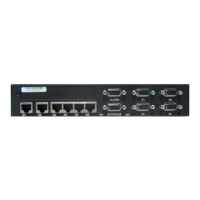
RJ45 10 or 100 Mbps Ethernet port for connection to
copper Ethernet capable devices or network.
Ethernet port numbering is from left (E1) to right
and not marked on the rear panel of the unit.
Ports E7 and E8
(optional)
LC Small Form Pluggable (SFP) 100 Mbps Ethernet
port for connection to fiber optic Ethernet capable
devices or Networks
Ports E9 and E10
(optional)
LC Small Form Pluggable 1000 Mbps Ethernet port for
connection to fiber optic Ethernet capable devices
or network
Ports S1- S16 RJ45 Connection to serial async devices. Configurable to
300, 600,1200, 2400, 4800, 9600, and 19.2, 28.8,
33.6, 38.4, 57.6, 115.2, 230.4 Kbps
W1
and
W2
RJ48 56/64 Kbps DDS CSU/DSU WAN connection
Refer to labeling on the
DS2000-IFR for WAN port
type
W1
and
W2
RJ48 T1/E1 CSU/DSU WAN connection
Refer to labeling on the
DS2000-IFR for WAN port
type
RS232 (DEBUG) DB15 (female) This is a factory test connection point only
E0 RJ45 Additional Ethernet port which can be used as
required for 10/100 Ethernet traffic
AUX1 RJ45 This is a factory test connection point only
S0 RJ69
(also called
10-pin RJ45)
Additional Sync/Async port which can used as
required for a connection to a serial device
CON RJ45 Console port for local management session
connections. Configured to operate at 9600 Baud,
7 bits, Even parity, one stop bit and is configured as
aDTE.
AUX2 DB15 (female) This port is not currently used
Power Connection Screws Nonpolarized power input.
Facility Ground
Point
Lug bolt Facility ground connection point