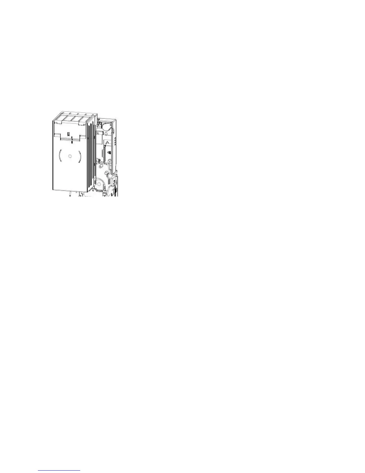
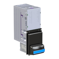
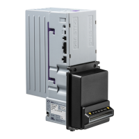
3.4.1 Cassette Fitting / Removal
To fit a note cassette to the GBA ST1 validator, ensure that the cassette lid is level with purple
cassette clip of the GBA ST1 body. Line up the four cassette locating studs with the four location
slots in the channel and push the cassette firmly towards the validator body. The studs will locate
into the joints. To ensure that the cassette latch has successfully re-engaged, press down on the
cassette lid. Remove the cassette by sliding the cassette clip forwards (away from the cassette)
and lifting the cassette away from the GBA ST1 unit.
3.4.1 Image of Cassette removed
3.4.2 Tamper Evident Lockable Cassettes
Each GBA ST1 note Cassette has the capacity for 2 locks to be fitted, preventing access to stored
notes. The procedure below gives step by step instructions on how to assemble and fit the
required lock.
Procedure;
1) Assemble all parts of the appropriate Cassette Lock Kit (Part number ASY-W-10295, Left or
ASY-W-10296, Right). Figure a, below, illustrates the correct component sequence and
orientation. Generally these components are supplied pre-assembled in a lock kit. Please
note that the lock will only function correctly if the cam (3) is fitted in the correct
orientation for the chosen lock position.
2) Tighten fully the screw (1) securing the lock cam to the lock body, ensuring that both plain
and shakeproof washers are in place. Do not tighten the M12 lock nut (2) at this stage.
3) Remove purple U-shaped break-out tabs from the stacker base using side cutters or safety
knife.
4) Ensuring the narrowest edge of the lock plate is uppermost (as per figure b), insert lock
assembly into one of the purple recessed areas of the stacker base (figure c)
5) Line up the 4 corner tabs of the lock assembly with the 4 cut out holes.
6) Firmly press the lock assembly into the 4 holes, ensuring it is located securely in place
(figure c).
7) Using a fine bladed tool, such as a screwdriver, fully tighten the M12 lock nut (2).