8.0 ELECTRICAL CONNECTIONS
Please note: care should be taken to avoid reversing the Ground and 12VDC connections, as this
will cause damage to the unit.
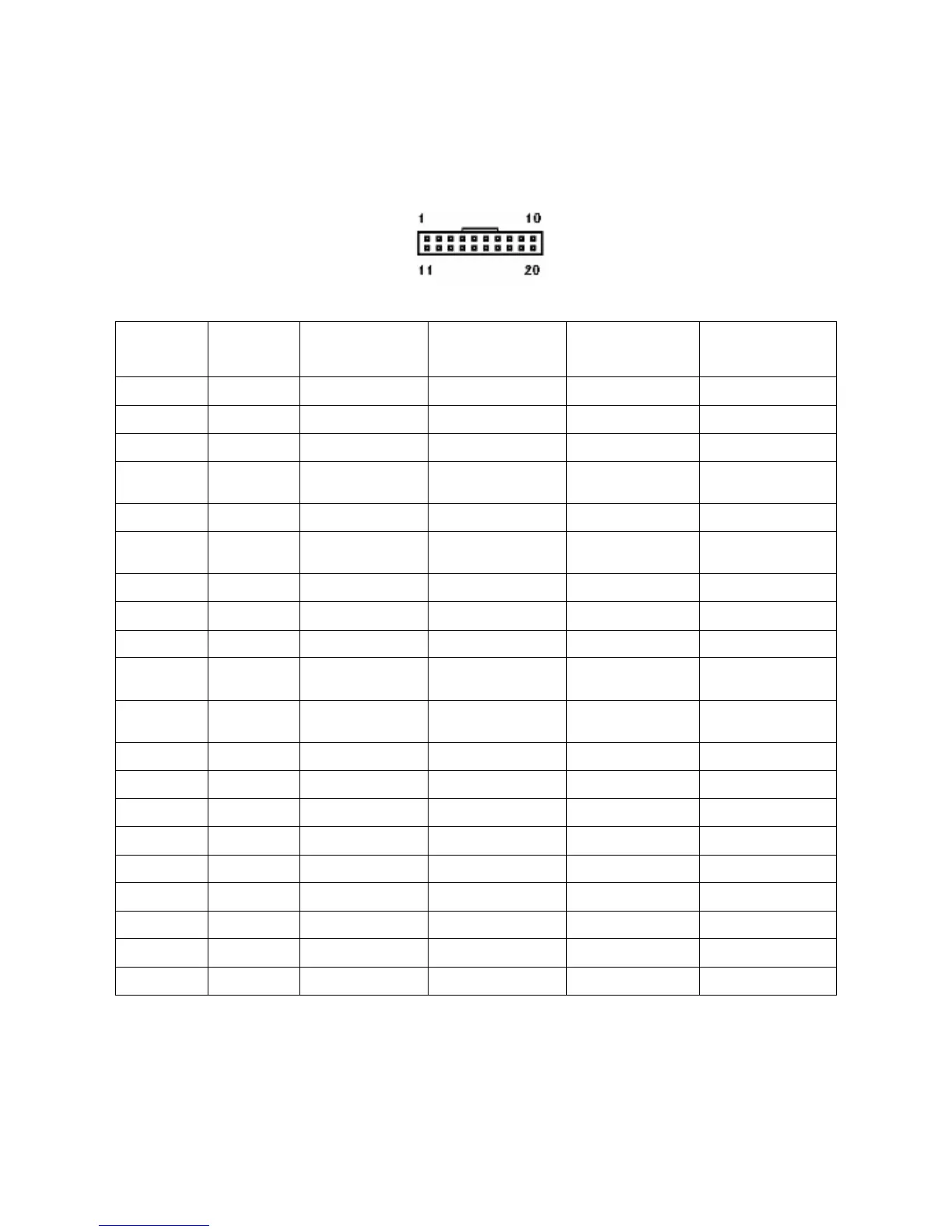
View of connector on GBA validator
Pin Parallel
Mars Serial
Pulse Serial
Interfaces
1
1
Grey /ABN Output /ABN Output /ABN Output n.c.
2
Orange n.c. /Serial Select (Low) Pulse (High) or n.c. n.c.
3
White /Vend 6 Output /Busy /Busy n.c.
4
Yellow /Escrow control Clears /ABN and
Stacker Full Signal
Clears /ABN and
Stacker Full Signal
n.c.
5
Green / Vend 5 Output TXD n.c. TXD
6
Brown n.c. Serial Send Signal
(/RTS)
n.c. n.c.
7
Black / Vend 3 Output Gnd n.c. n.c.
8
Red / Vend 4 Output n.c. n.c. n.c.
9
Whi/Blk/Grn n.c. n.c. n.c. RXD
10
Blue Inhibit Control
Input (/Enable)
Inhibit Control Input
(/Enable)
Inhibit Control
Input (/Enable)
n.c.
11
Violet / Vend 1 Output Confirm Signal To
Start Serial (/CTS)
n.c. n.c.
12
Whi/Vio n.c. n.c. /Pulse O/P n.c.
13
Whi/Gry / Vend 2 Output n.c. n.c. n.c.
14
Whi/Blk Ground Ground Ground Ground
15
Whi/Blk Ground Ground Ground Ground
16
2
Whi/Red 12 VDC + 12 VDC + 12 VDC + 12 VDC +
17
Whi/Red 12 VDC + 12 VDC + 12 VDC + 12 VDC +
18
Whi/Yel PDT Terminal PDT Terminal PDT Terminal PDT Terminal
19
Whi/Grn PDT Terminal PDT Terminal PDT Terminal PDT Terminal
20
Whi/Blu PDT Terminal PDT Terminal PDT Terminal PDT Terminal
Note: where a description is preceded by a “/” then that signal is active low.
n.c. = not connected
1. For cctalk
®
interface, please note that TXD & RXD can both be connected to the DATA line
of the host machine.
2. If the ST1 is used in Low Power Mode, only connect the 12 Volt supply to pin 17.