6–44 345 TRANSFORMER PROTECTION SYSTEM – INSTRUCTION MANUAL
S3 PROTECTION CHAPTER 6: SETPOINTS
BLOCK 1/2/3
For details see Common setpoints
.
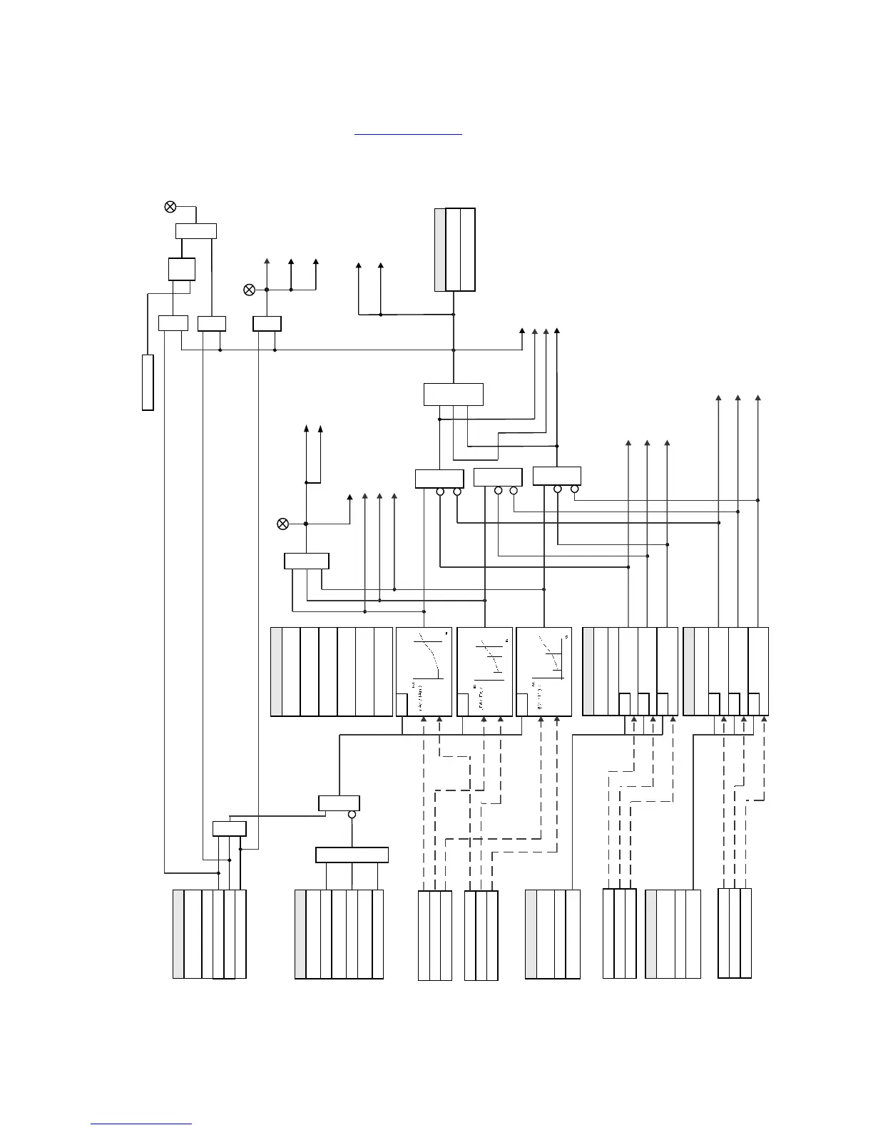
Figure 6-20: Percent Differential Protection logic diagram
SETPOINT
Phase A current (IA2d)
SETPOINT
PERCENT DIFF
FUNCTION:
Disabled = 0
Latched Alarm
MINIMUM PICKUP:
AND
Phase B current (IB2d)
Phase C current (IC2d)
Operate Output Relay 1
(W1 BKR TRIP)
LED: ALARM
LED: TRIP
Event Recorder
Transient Recorder
Alarm
OR
OR
Differential 2nd Harmonic
AND
SETPOINT
Do Not Operate, Operate
OUTPUT RELAY X
Trip
AND
SETPOINT
BLOCK 1:
Off = 0
BLOCK 2:
Off = 0
BLOCK 3:
Off = 0
OR
Message
OR
Trip
(To Breaker Failure)
Phase A Diff Current (IAd)
Differential Currents
Restraint Currents
SETPOINT
INRUSH INHIBIT
FUNCTION
Disabled = 0
2nd harmonic
SLOPE 1
BREAKPOINT 1
BREAKPOINT 2
SLOPE 2
INRUSH INHIBIT LEVEL
RUN
RUN
RUN
INRUSH INHIBIT LEVEL
INRUSH INHIBIT MODE
IA2d = LEVEL
SETPOINT
RUN
RUN
SETPOINT
OVEREXCITATION
INHIBIT FUNCTION
Disabled = 0
5th harmonic =1
Phase A current (IA5d)
Phase B current (IB5d)
Phase C current (IC5d)
Differential 5th Harmonic
OVEREXC INHIBIT LEVEL
SETPOINT
RUN
RUN
RUN
AND
AND
AND
PCNT DIFF PH C PKP
Message
Event Recorder
Transient Recorder
LED: PICKUP
OR
RESET
Command
AND
S
R
LATCH
PCNT DIFF PH A OP
PCNT DIFF PH B PKP
PCNT DIFF PH A PKP
PCNT DIFF PKP
RUN
Operate Output Relay 2
(W2 BKR TRIP)
Event Recorder
2ND HMNC DIFF PH A
Event Recorder
Phase B Diff Current (IBd)
Phase C Diff Current (ICd)
Phase A Rest Current (IAr)
Phase B Rest Current (IBr)
Phase C Rest Current (ICr)
IB2d = LEVEL
IC2d = LEVEL
IA5d = LEVEL
IB5d = LEVEL
IC5d = LEVEL
2ND HMNC DIFF PH B
2ND HMNC DIFF PH C
5TH HMNC DIFF PH A
5TH HMNC DIFF PH B
5TH HMNC DIFF PH C
PCNT DIFF PH B OP
PCNT DIFF PH C OP
PCNT DIFF OP
897803A1.cdr