3–20 345 TRANSFORMER PROTECTION SYSTEM – INSTRUCTION MANUAL
SOFTWARE SETUP CHAPTER 3: INTERFACES
Connecting to the
relay
Now that the communications parameters have been properly configured, the user can
easily communicate with the relay.
1. Expand the Site list by double clicking on the site name or clicking on the «+» box to
list the available devices for the given site.
2. Desired device trees can be expanded by clicking the «+» box. The following list of
headers is shown for each device:
Device Definition
Actual Values
Quick Setup
Setpoints
Maintenance.
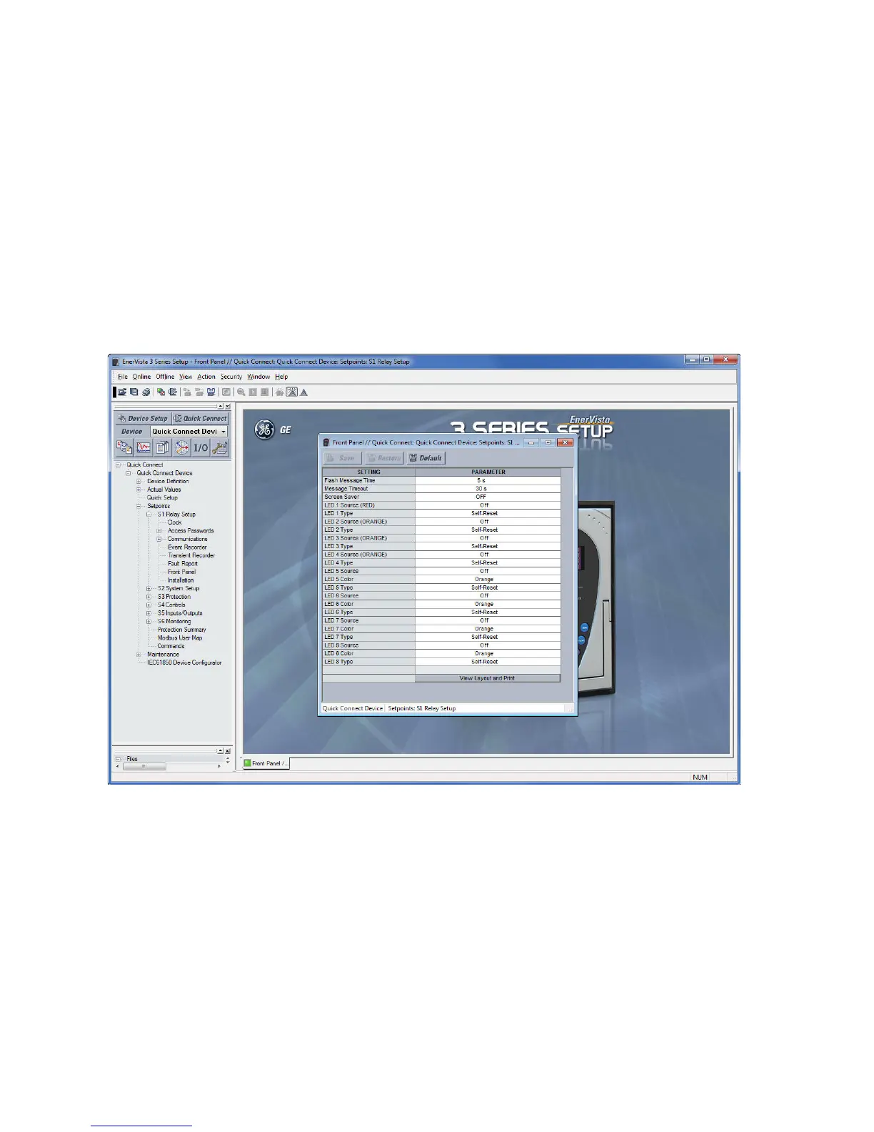
3. Expand the SETTINGS > RELAY SETUP list item and double click on Front Panel to open
the Front Panel settings window as shown:
4. The Front Panel settings window opens with a corresponding status indicator on the
lower left of the EnerVista 3 Series Setup window.
5. If the status indicator is red, verify that the serial, USB, or Ethernet cable is properly
connected to the relay, and that the relay has been properly configured for
communications (steps described earlier).
The Front Panel settings can now be edited, printed, or changed. Other setpoint and
command windows can be displayed and edited in a similar manner. "Actual Values"
windows are also available for display. These windows can be arranged, and resized at
will.