2–20 345 TRANSFORMER PROTECTION SYSTEM – INSTRUCTION MANUAL
ELECTRICAL INSTALLATION CHAPTER 2: INSTALLATION
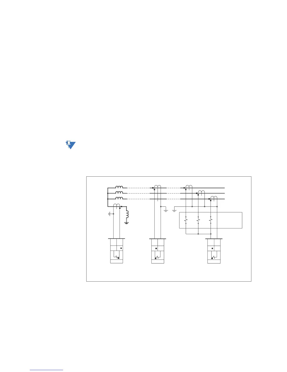
Ground and sensitive ground CT inputs
Two ground inputs - one per winding - are referred to throughout this manual as the
Ground Current or Sensitive Ground Current inputs. Before making ground connections,
consider that the relay automatically calculates the neutral (residual) current from the sum
of the three phase current phasors. The following figures show three possible ground
connections (or three possible sensitive ground connections).
The ground inputs (Terminals D8 and E8 for W1, and D12 and E12 for W2) are used in
conjunction with a Zero Sequence CT as source, or in the neutral of wye-connected source
CTs. When using the residual connection set the GROUND CT PRIMARY setpoint to a value
equal to the PHASE CT PRIMARY setpoint.
In cases where the relay is equipped with sensitive ground CT (terminals D8 and E8 for W1,
and D12 and E12 for W2) the sensitive ground current input is intended for use with a CT in
a source neutral of a high-impedance grounded system, or on ungrounded systems. On
ungrounded systems it is connected residually with the phase current inputs. In this case,
the SENSTV GND CT PRIMARY setpoint should be programmed to a value equal to the
PHASE CT PRIMARY setpoint. The sensitive ground current input can be connected to a
Zero Sequence CT for increased sensitivity and accuracy when physically possible in the
system.
NOTE:
The Sensitive Ground input must only be used on systems where the maximum ground
current does not exceed current input specification.
The ground CT wiring in the figure below, shows 3 possible ways for wiring the Winding 1
ground CT (terminals D8, E8). The Winding 2 ground CT wiring (terminals D12, E12) is similar.
Figure 2-24: Ground/Sensitive Ground wiring
For Winding 2 ground CT, use relay terminals D12-E12 in the same wiring configuration as
shown above for Winding 1.
Transformer Winding 1
897730A1.CDR
A
B
C
GROUND CURRENT INPUT
345
PHASE CURRENT
INPUTS
A B C
GROUND CURRENT INPUT
WITH ZERO SEQUENCE CT
GROUND CURRENT INPUT
WITH RESIDUAL CONNECTION
E8 D8
G
GROUND
I N NI
G
E5
D5
D6
E6
D7
E7
G
IN
GROUND
D8 E8
GROUND
D8E8