CHAPTER 6: SETPOINTS S2 SYSTEM SETUP
345 TRANSFORMER PROTECTION SYSTEM – INSTRUCTION MANUAL 6–35
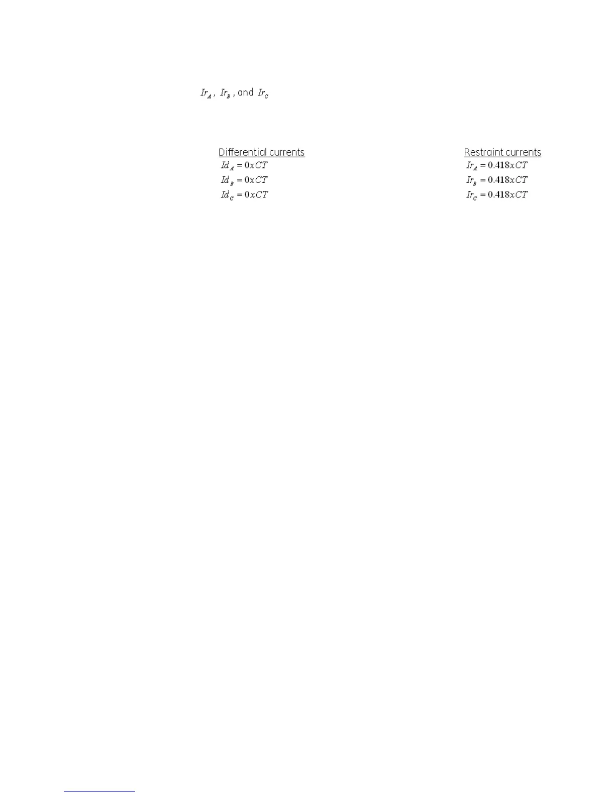
are the phase restraint currents.
Per the example, the per-phase differential and restraint currents would be as follows:
Winding breakers
The status of the Winding 1 breaker is monitored by the 345 relay using the status of either
one or two contact inputs, 52a (CI#1) and 52b (CI#2), wired to the Winding 1 breaker
auxiliary contacts 52a and 52b, and the status of the Winding 2 breaker 52a (CI#3) and 52b
(CI#4) wired to Winding 2 breaker aux contacts 52a and 52b respectively (see below).
The following path is available using the keypad. For instructions on how to use the
keypad, please refer to Chapter 3 - Working with the Keypad.
PATH:
SETPOINTS > S2 SYSTEM SETUP > WNDG 1 BREAKER
52a CONTACT
Range: Disabled, Contact Input 1
Default: Disabled
Select Contact Input 1 [52a (CI#1)] if connected to breaker auxiliary contact 52a.
52b CONTACT
Range: Disabled, Contact Input 2
Default: Disabled
Select Contact Input 2 [52b (CI#2)] if connected to breaker auxiliary contact 52b.
BKR CONNECTED
Range: Contact Input 5 to 10, Disabled
Default: Disabled
Select a contact input to show whether the breaker is connected (Racked-in, or
disconnect switches switched-on), or disconnected (racked-out, or disconnect switches
switched-off) to the system.
PATH:
SETPOINTS > S2 SYSTEM SETUP > WNDG 2 BREAKER
52a CONTACT
Range: Disabled, Contact Input 3
Default: Disabled
Select Contact Input 3 [52a (CI#3)] if connected to Winding 2 breaker auxiliary contact
52a.
52b CONTACT
Range: Disabled, Contact Input 4
Default: Disabled
Select Contact Input 4 [52b (CI#4)] if connected to Winding 2 breaker auxiliary contact
52b.