6–82 345 TRANSFORMER PROTECTION SYSTEM – INSTRUCTION MANUAL
S4 CONTROLS CHAPTER 6: SETPOINTS
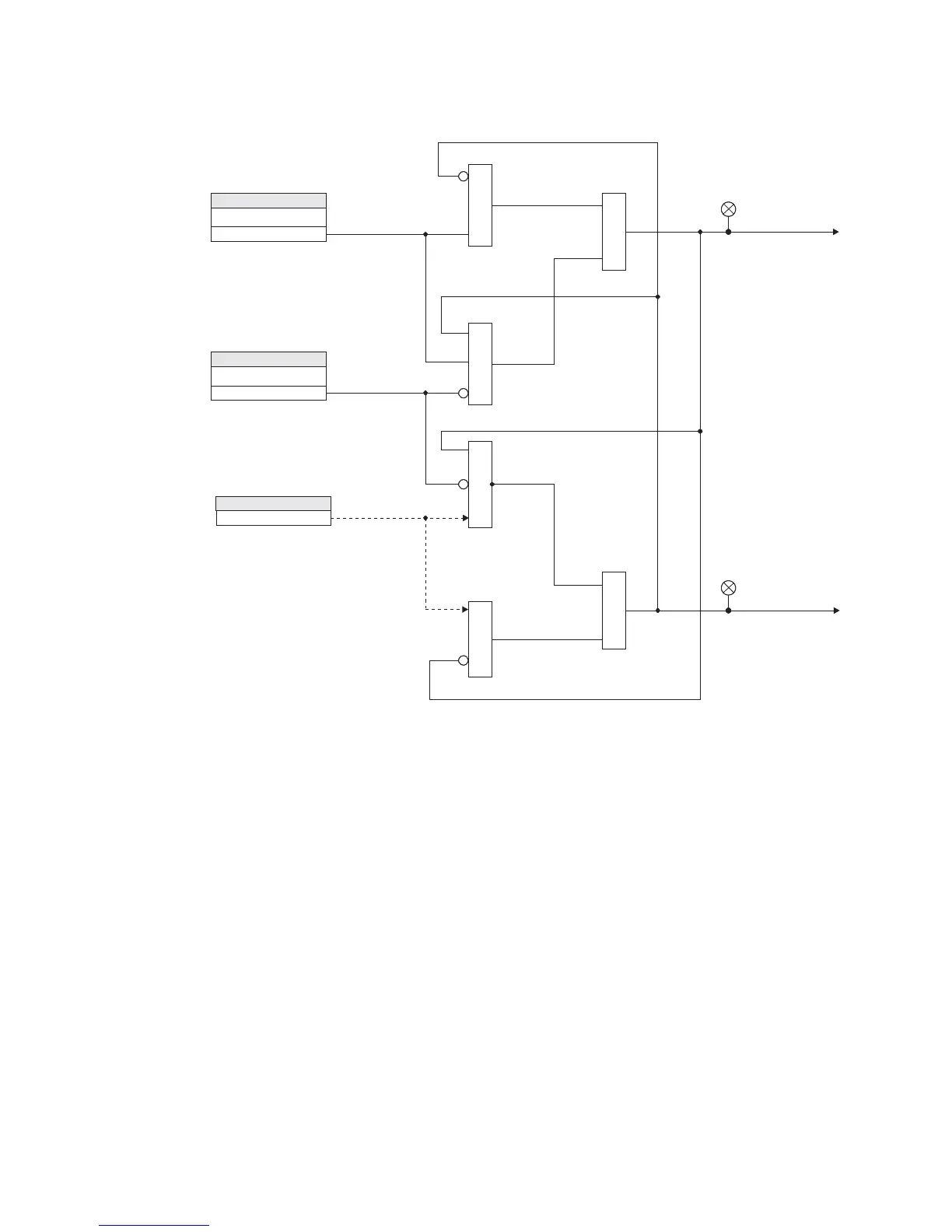
Figure 6-35: Switching setpoint groups - Logic diagram
Virtual inputs
There are 32 virtual inputs that can be individually programmed to respond to input
commands entered via the relay keypad, or by using communication protocols.
PATH:
SETPOINTS > S4 CONTROLS > VIRTUAL INPUTS.
VIRTUAL INPUT 1
Range: Off, On
Default: Off
The state of each virtual input can be controlled under
SETPOINTS > S4 CONTROL > VIRTUAL
INPUTS
menu. For this purpose, each of the virtual inputs selected for control need be
“Enabled” under
SETPOINTS > S5 INPUTS/OUTPUTS > VIRTUAL INPUTS, and its type “Self-
Reset” or “Latched” specified.
If Self-Reset type was selected, entering “On” command will lead to a pulse of one
protection pass. To prolong the time of the virtual input pulse, one can assign it as a trigger
source to a Logic Element with a dropout timer set to the desired pulse time. If “Latched”
type is selected, the state of the virtual input will be latched, upon entering “On” command.
Refer to the logic diagram in the
S5 INPUTS/OUTPUTS > VIRTUAL INPUTS section for more
details.
SETPOINT
SET GROUP 2 ACTIVESET GROUP 2 ACTIVE
Off
SETPOINT
BLK GROUP CHANGEBLK GROUP CHANGE
Off
Use Setpoint Group 2Use Setpoint Group 2
Default to Setpoint Group 1Default to Setpoint Group 1
Group 1 ActiveGroup 1 Active
ACTUAL VALUESACTUAL VALUES
LED: Setpoint Group 2LED: Setpoint Group 2
LED: Setpoint Group 1LED: Setpoint Group 1
897791.cdr
AND
AND
AND
AND
OR
OR