6–48 345 TRANSFORMER PROTECTION SYSTEM – INSTRUCTION MANUAL
S3 PROTECTION CHAPTER 6: SETPOINTS
maximum measured line current (Imax) to produce a percent slope value. The slope setting
allows the user to determine the sensitivity of the element based on the class and quality
of the CTs used.
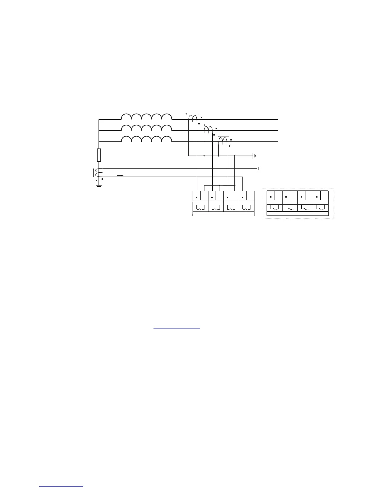
The figure below shows the typical wiring between the winding CTs and the 345 CT
terminals to assure the correct performance of the protection. The restricted earth fault
protection is also available for delta windings with in-zone grounding transformer, or for
Delta corner grounded windings.
The 345 RGF protection includes ground current supervision mechanism o provide more
security during external non-ground faults associated with CT saturation, that may result
into spurious neutral current, and may jeopardize the security of the RGF protection. When
the GND CURRENT SUPERVISION setting is selected as “Enabled”, the algorithm checks if
the ground current measured by the relay satisfies the selected GND CURRENT
SUPERVISION LEVEL, before making operation decision. The ground current supervision is
not active if the GND CURRENT SUPERVISION is selected as “Disabled”. The RGF protection
works without the supervision as well.
PATH:
SETPOINTS > S3 PROTECTION > S3 PROTECTION GROUP 1(2) > RESTRICTED GROUND
FAULT 1(2)
RGF FUNCTION
Range: Disabled, Latched Alarm, Alarm, Trip
Default: Disabled
For details see Common setpoints
.
Output relays #1 “R1 TRIP” (and #2 “R2 TRIP”) will operate only when the Trip setting is
selected, and the Restricted Ground Fault protection is operational.
CT INPUTS
Range: CT (W1), CT(W2)
Default:CT (W1)
This setting defines the winding three-phase and ground currents used by the RGF
function.
RGF PICKUP
Range: 0.02 to 20 x CT (W1) in steps of 0.01
Default: 0.10 x CT (W1)
This setting defines the minimum pickup level of the ground differential current required
for operation. The pickup value is expressed in times phase CT primary rating.
E5 D5
Ia
E6 D6
Ib
E7 D7
Ic
E8 D8
Ig
Winding 1 Current Inputs - CT (W1)
E9 D9
Ia
E10 D10
Ib
E11 D11
Ic
E12 D12
Ig
Winding 2 Current Inputs - CT (W2)
Transformer Winding
Rg
IA
IB
IC
IG
Ig