SETPOINT
SETPOINT
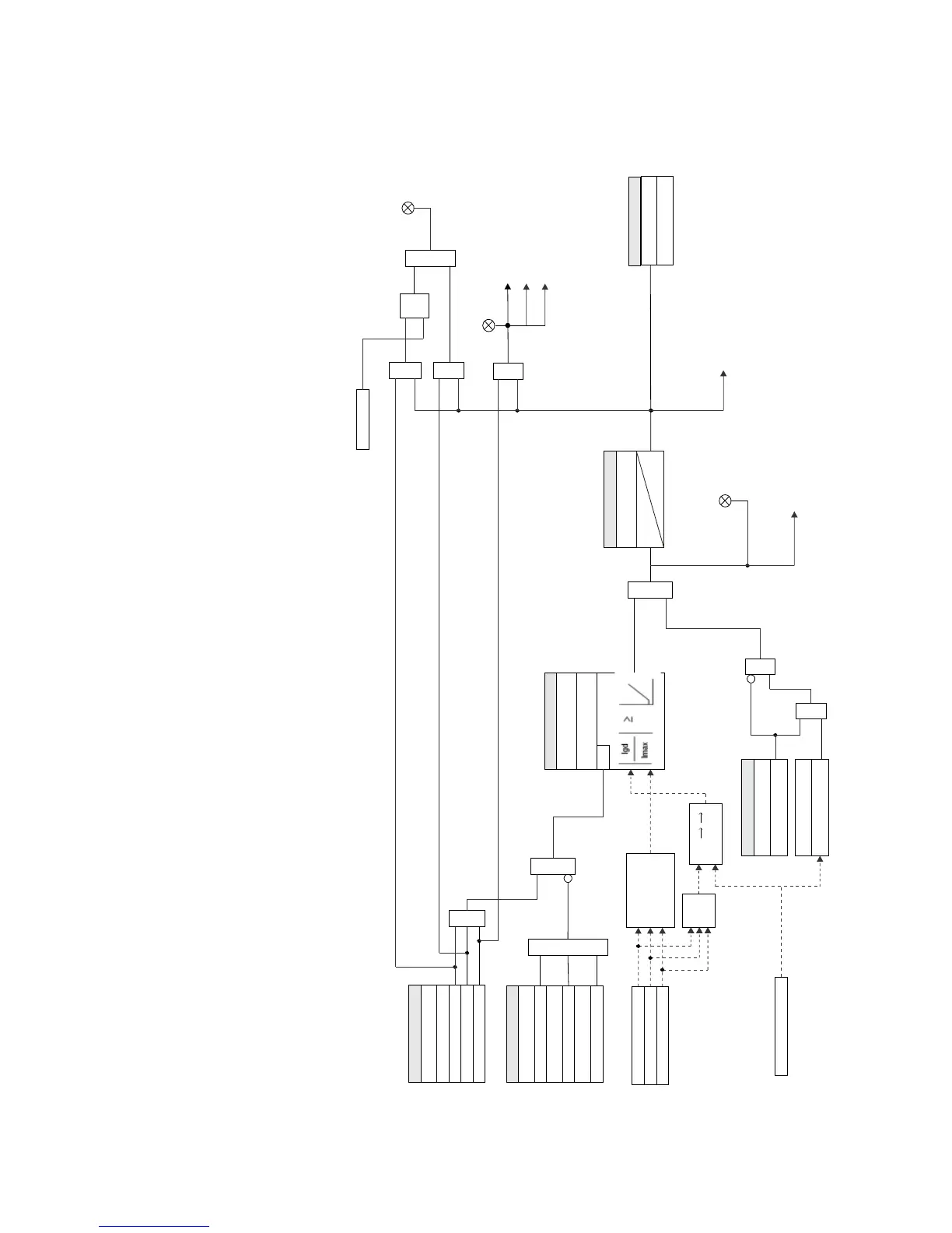
RGF FUNCTION:
Disabled = 0
Latched Alarm
RGF SLOPE:
AND
LED: TRIP
Alarm
OR
Trip
AND
SETPOINT
BLOCK 1:
Off = 0
BLOCK 2:
Off = 0
BLOCK 3:
Off = 0
OR
W1(2) Phase A current (Ia)
W1(2) Phase B current (Ib)
W1(2) Phase C current (Ic)
Winding Phase Currents
RUN
Imax = max (Ia,Ib,Ic)
RGF PICKUP:
LED: PICKUP
RGF PKP
Message and Event Recorder:
RGF OP
Message and Event Recorder
RGF PKP TIME DELAY:
SETPOINT
t
PKP
0
AND
OR
LED: ALARM
RESET
Command
AND
S
R
LATCH
W1(2) Ground current (Ig)
Winding Ground Current
In = 3I0
Igd = I 3I0 + Ig I
SETPOINT
GND CURRENT SUPV:
Disabled = 0, Enabled = 1
GND CURNT SPV LEVEL
Ig >
LEVEL
(x CT1)
AND
OR
AND
Operate Output Relay 1 (W1 BKR TRIP)
Operate Output Relay 2 (W2 BKR TRIP)
SETPOINT
Do Not Operate, Operate
OUTPUT RELAY X
897806A1.cdr
TRIP (To Breaker Failure)