CHAPTER 7: MAINTENANCE M3 BREAKER MAINTENANCE
345 TRANSFORMER PROTECTION SYSTEM – INSTRUCTION MANUAL 7–5
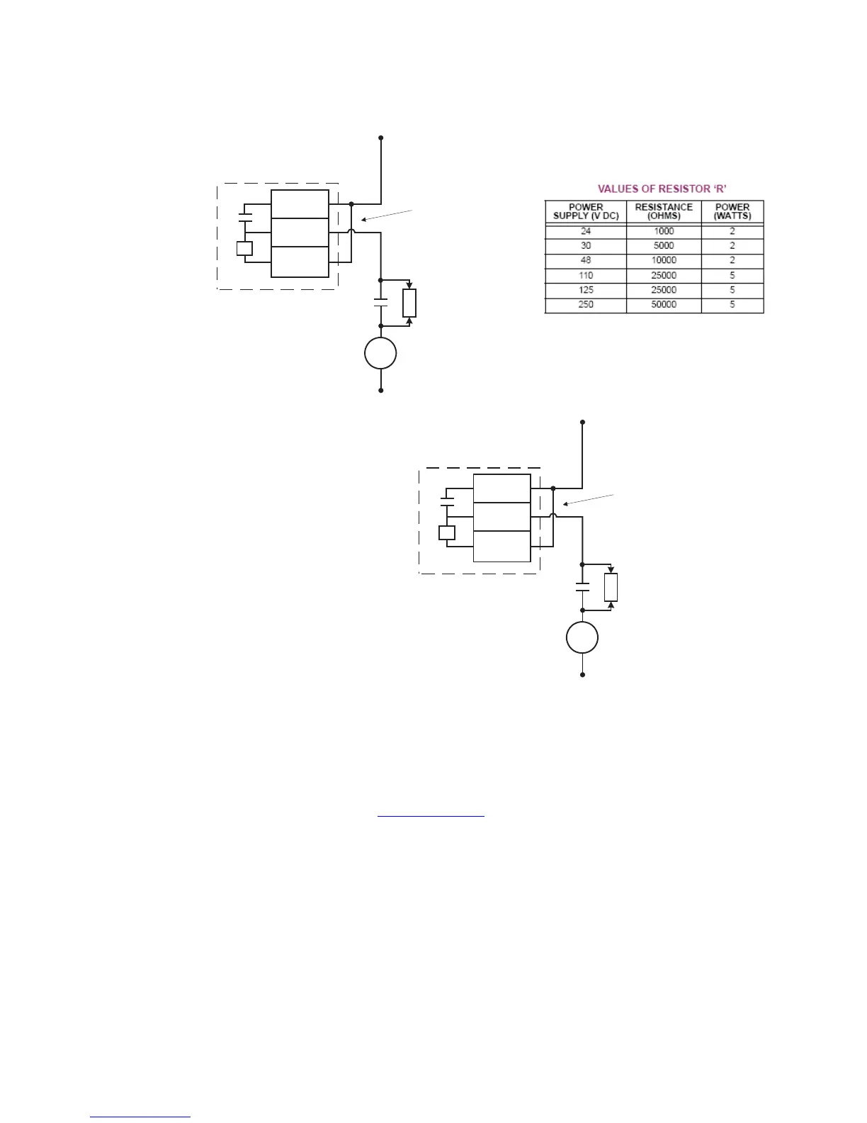
Figure 7-4: Trip circuits with continuous monitoring
The following path is available using the keypad. For instructions on how to use the
keypad, please refer to Chapter 3 - Working with the Keypad.
PATH:
MAINTENANCE > M3 BKR MAINTENANCE > W1(W2) BKR TRIP
RLY1(2) COIL FUNCTION
Range: Disabled, Alarm, Latched Alarm
Default: Disabled
For details see Common setpoints
.
The “ALARM” and “MAINTENANCE” LEDs will light up upon detection of a RLY1(2) coil
circuitry problem.
RLY1(2) COIL DELAY
Range: 1 to 10 sec in steps of 1 sec
Default: 5 s
This setting defines the RLY1(2) Coil Monitor Delay, before targets appear on the display,
“ALARM” and “MAINTENANCE” LEDs light up on the front panel, and selected output
relays operate.
Trip
Coil
DC -
R
By-pass
resistor
52a contact
External
jumper
V
A2
B3
A3
DC +
Output Relay 1 (TRIP)
897787.cdr
Trip
Coil
DC -
R
By-pass
resistor
52a contact
External
jumper
V
B4
A4
B5
DC +
Output Relay 2 (TRIP)
897788.cdr