5-148 F35 Multiple Feeder Protection System GE Multilin
5.6 CONTROL ELEMENTS 5 SETTINGS
5
The trip bus element allows aggregating outputs of protection and control elements without using FlexLogic™ and assign-
ing them a simple and effective manner. Each trip bus can be assigned for either trip or alarm actions. Simple trip condition-
ing such as latch, delay, and seal-in delay are available.
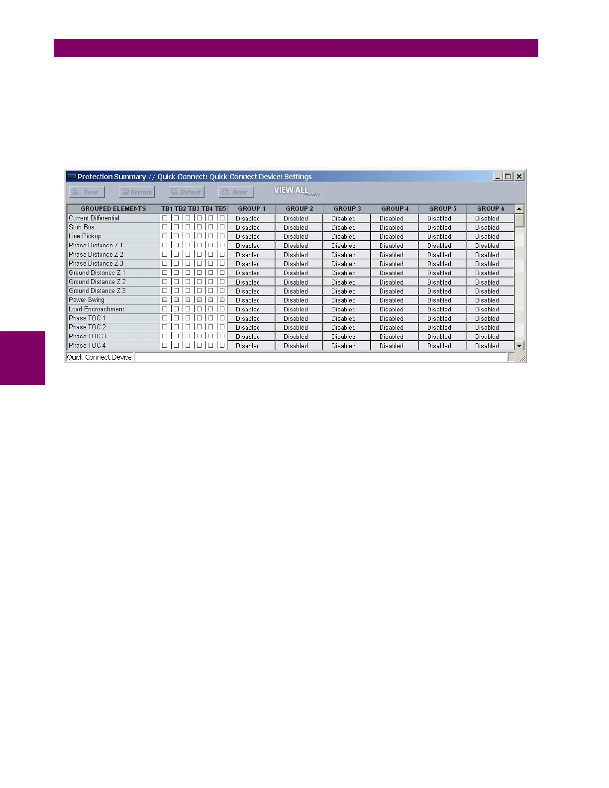
The easiest way to assign element outputs to a trip bus is through the EnerVista UR Setup software A protection summary
is displayed by navigating to a specific protection or control protection element and checking the desired bus box. Once the
desired element is selected for a specific bus, a list of element operate-type operands are displayed and can be assigned
to a trip bus. If more than one operate-type operand is required, it may be assigned directly from the trip bus menu.
Figure 5–75: TRIP BUS FIELDS IN THE PROTECTION SUMMARY
The following settings are available.
• TRIP BUS 1 BLOCK: The trip bus output is blocked when the operand assigned to this setting is asserted.
• TRIP BUS 1 PICKUP DELAY: This setting specifies a time delay to produce an output depending on how output is
used.
• TRIP BUS 1 RESET DELAY: This setting specifies a time delay to reset an output command. The time delay should be
set long enough to allow the breaker or contactor to perform a required action.
• TRIP BUS 1 INPUT 1 to TRIP BUS 1 INPUT 16: These settings select a FlexLogic™ operand to be assigned as an
input to the trip bus.
• TRIP BUS 1 LATCHING: This setting enables or disables latching of the trip bus output. This is typically used when
lockout is required or user acknowledgement of the relay response is required.
• TRIP BUS 1 RESET: The trip bus output is reset when the operand assigned to this setting is asserted. Note that the
RESET OP operand is pre-wired to the reset gate of the latch, As such, a reset command the front panel interface or via
communications will reset the trip bus output.