5–24 745 TRANSFORMER PROTECTION SYSTEM – INSTRUCTION MANUAL
AUTO-CONFIGURATION CHAPTER 5: SETPOINTS
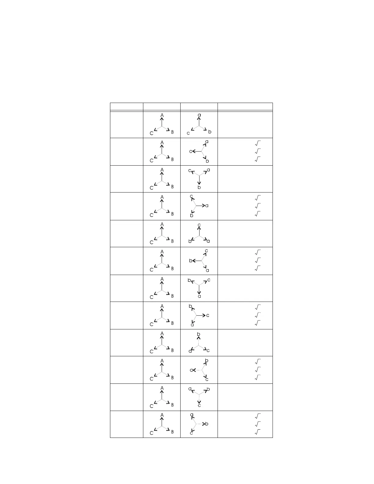
5.2.7 Phase Shifts
The table below provides additional information about the Phase shift column in Table 5–
1: Transformer types on page 5–13 and represents an assumed ABC phasor rotation. For
transformers connected to a system with a phasor rotation of ACB, interchange all B (b)
and C (c) designations.
Table 5–2: Phase shifts
Phase shift Input phasors Output phasors Phasor
transformation
0° a = A
b = B
c = C
30° lag
a = (A – C) /
b = (B – A) /
c = (C – B) /
60° lag a = –C
b = –A
c = –B
90° lag
a = (B – C) /
b = (C – A) /
c = (A – B) /
120° lag a = B
b = C
c = A
150° lag
a = (B – A) /
b = (C – B) /
c = (A – C) /
180° lag a = –A
b = –B
c = –C
210° lag
a = (C – A) /
b = (A – B) /
c = (B – C) /
240° lag a = C
b = A
c = B
270° lag
a = (C – B) /
b = (A – C) /
c = (B – A) /
300° lag a = –B
b = –C
c = –A
330° lag
a = (A – B) /
b = (B – C) /
c = (C – A) /