3–10 745 TRANSFORMER PROTECTION SYSTEM – INSTRUCTION MANUAL
TYPICAL WIRING CHAPTER 3: INSTALLATION
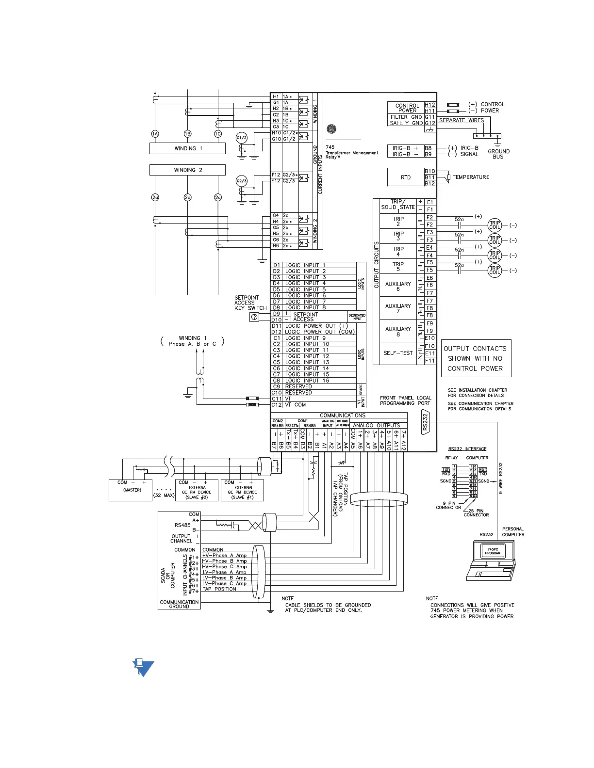
3.2.3 Wiring Diagrams
FIGURE 3–11: Typical wiring for two-winding transformer
Note
Since the relay takes one voltage input, power and var metering is not accurate for
unbalanced conditions. In addition, depending on which winding the VT is on, the power
flows and vars displayed may be opposite in direction to the actual system flow; e.g. in the