CHAPTER 3: INSTALLATION TYPICAL WIRING
745 TRANSFORMER PROTECTION SYSTEM – INSTRUCTION MANUAL 3–11
case of a generator step-up transformer, depending on the relay winding assignments and
which side of the transformer the VT is connected to, the power may be negative when the
generator is producing positive MW. This can be corrected by reversing the voltage input
into C11 and C12.
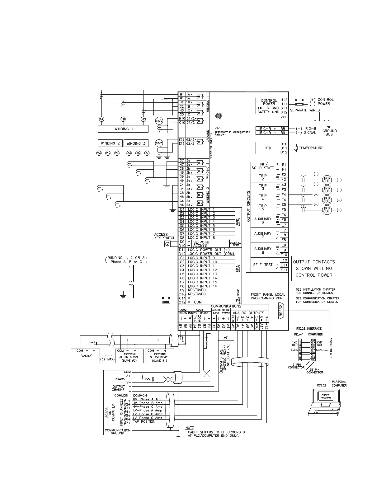
FIGURE 3–12: Typical wiring for three-winding transformer