745 TRANSFORMER PROTECTION SYSTEM – INSTRUCTION MANUAL 3–1
745 Transformer Protection
System
Chapter 3: Installation
GE
Grid Solutions
Instal lation
3.1 Drawout Case
3.1.1 Case Description
The 745 is packaged with a drawout relay and a companion case. The case provides
mechanical protection for the drawout portion, and is used to make permanent electrical
connections to external equipment. Where required, case connectors are fitted with
mechanisms, such as automatic CT shorting, to allow the safe removal of the relay from an
energized panel. There are no electronic components in the case.
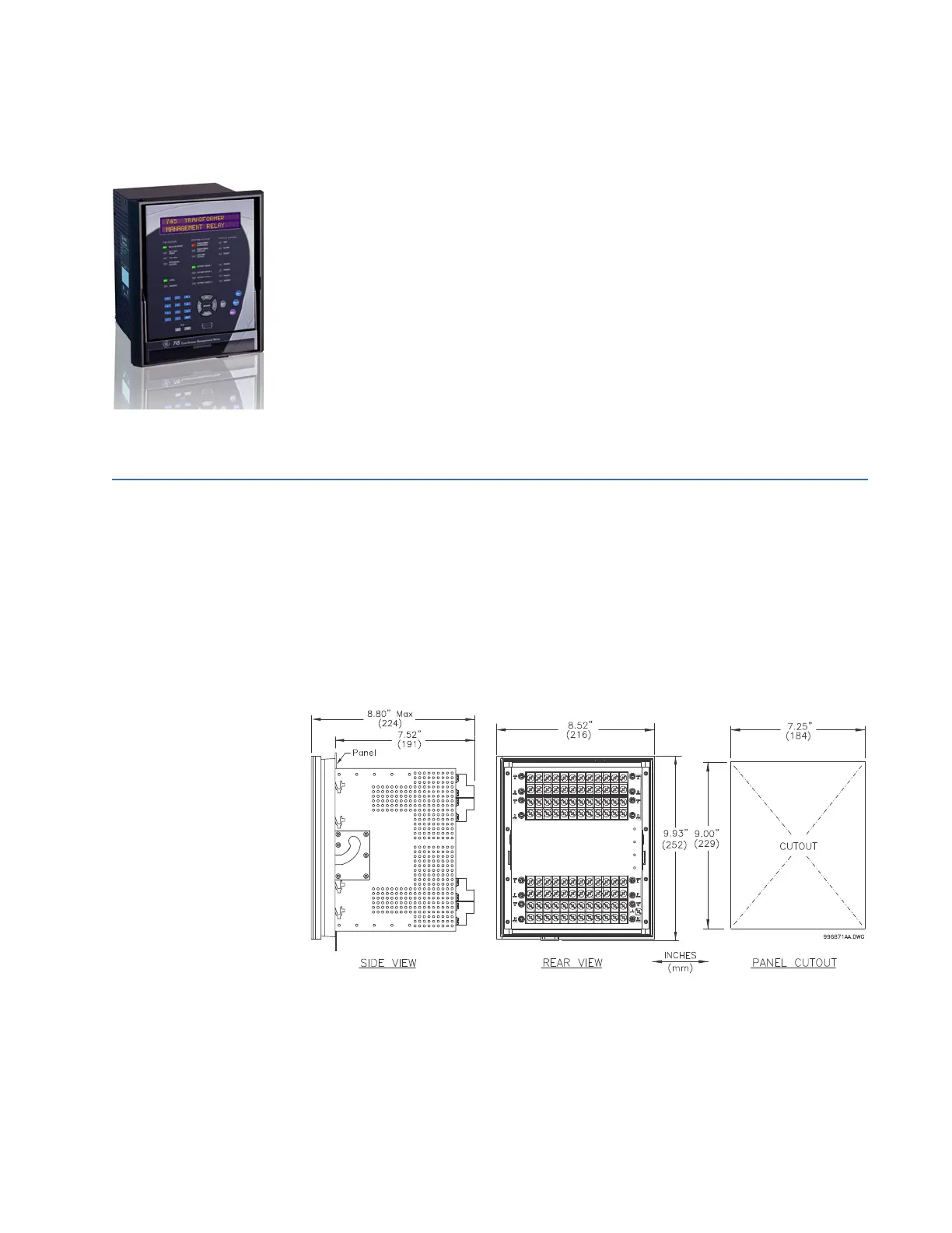
FIGURE 3–1: Case dimensions