CHAPTER 3: INSTALLATION TYPICAL WIRING
745 TRANSFORMER PROTECTION SYSTEM – INSTRUCTION MANUAL 3–15
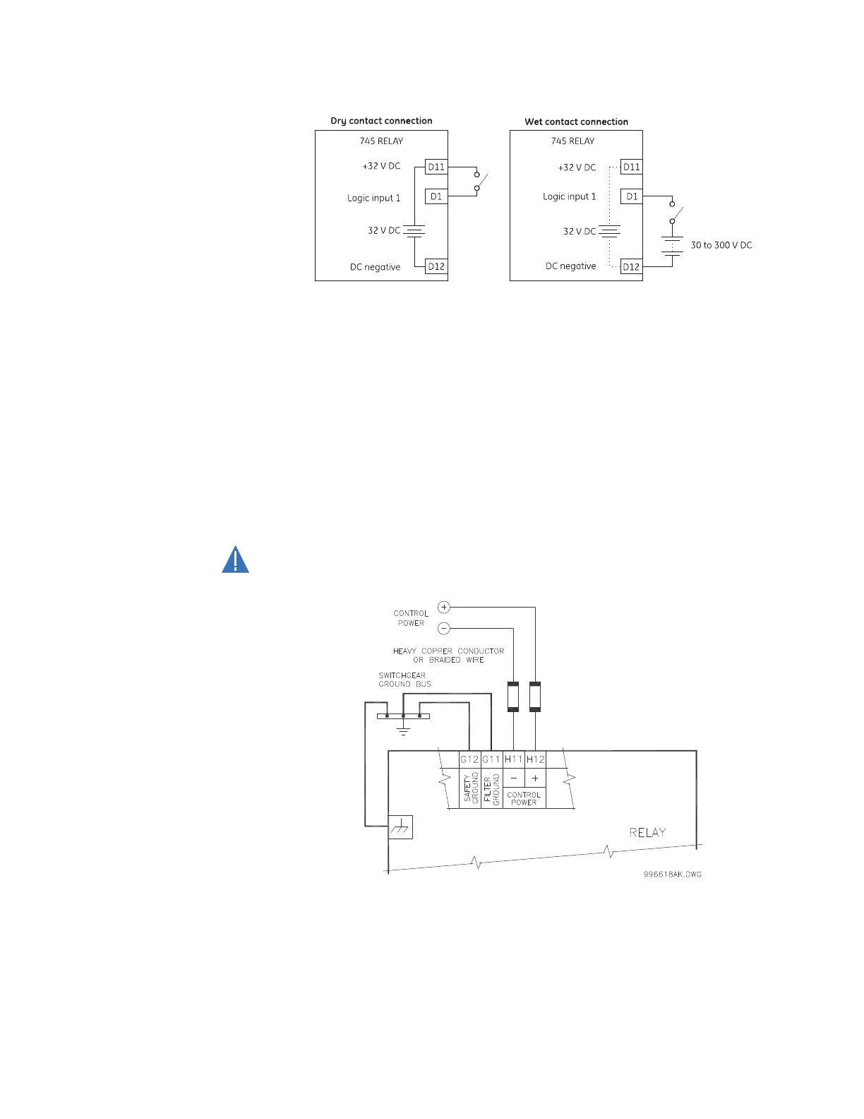
FIGURE 3–14: Dry and wet contact connections
3.2.8 Control Power
The label found on the left side of the relay specifies its order code or model number. The
installed power supply operating range will be one of the following.
LO: 25 to 60 V DC or 20 to 48 V AC
HI: 88 to 300 V DC or 70 to 265 V AC
Ensure the applied control voltage matches the requirements of the relay’s switching
power supply. For example, the HI power supply will work with any DC voltage from 88 to
300 V, or any AC voltage from 70 to 265 V. The internal fuse may blow if the applied voltage
exceeds this range.
Control power supplied to the relay must match the installed power supply range. If the
applied voltage does not match, damage to the unit may occur.
FIGURE 3–15: Control power connection
Extensive filtering and transient protection are built into the 745 to ensure proper
operation in harsh industrial environments. Transient energy must be conducted back to
the source through the filter ground terminal. A separate safety ground terminal is
provided for dielectric strength (hi-pot) testing.