3–6 745 TRANSFORMER PROTECTION SYSTEM – INSTRUCTION MANUAL
DRAWOUT CASE CHAPTER 3: INSTALLATION
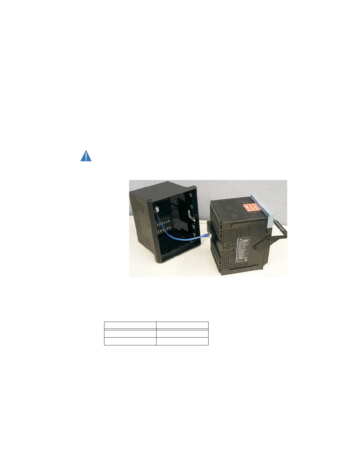
3.1.5 Ethernet connection
If using the 745 with the Ethernet 10Base-T option, ensure that the network cable is
disconnected from the rear RJ45 connector before removing the unit from the case. This
prevents any damage to the connector.
The unit may also be removed from the case with the network cable connector still
attached to the rear RJ45 connector, provided that there is at least 16 inches of network
cable available when removing the unit from the case. This extra length allows the network
cable to be disconnected from the RJ45 connector from the front of the switchgear panel.
Once disconnected, the cable can be left hanging safely outside the case for re-inserting
the unit back into the case.
The unit may then be re-inserted by first connecting the network cable to the units' rear
RJ45 connector (see step 3 of Unit Withdrawal and Insertion on page 3–3).
Ensure that the network cable does not get caught inside the case while sliding in the
unit. This may interfere with proper insertion to the case terminal blocks and damage
the cable.
FIGURE 3–9: Ethernet cable connection
To ensure optimal response from the relay, the typical connection timeout should be set as
indicated in the following table:
TCP/IP sessions Timeout setting
up to 2 2 seconds
up to 4 3 seconds