CHAPTER 3: INSTALLATION TYPICAL WIRING
745 TRANSFORMER PROTECTION SYSTEM – INSTRUCTION MANUAL 3–9
Note
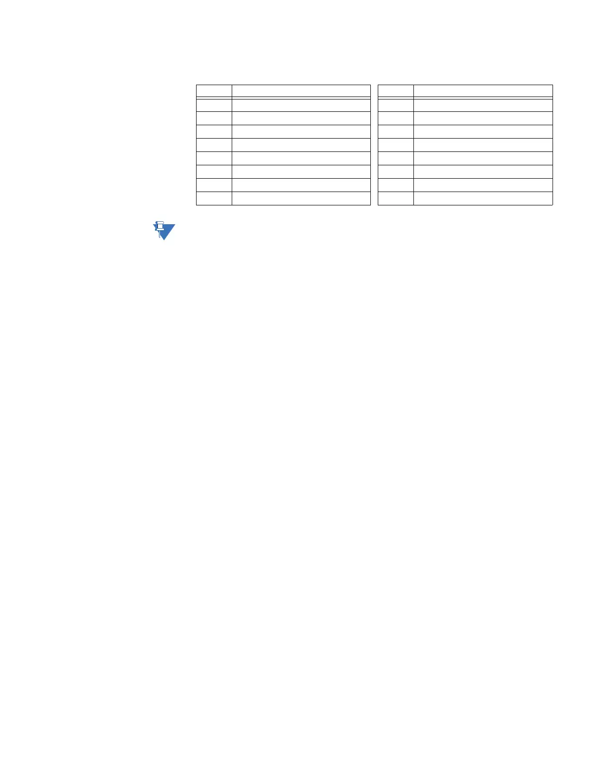
The symbol indicates the high side of CT and VT terminals
D5 Logic input 5 (+) H5 Phase B: winding 2 CT
D6 Logic input 6 (+) H6 Phase C: winding 2 CT
D7 Logic input 7 (+) H7 Phase A: winding 3 CT
D8 Logic input 8 (+) H8 Phase B: winding 3 CT
D9 Setpoint access (+) H9 Phase C: winding 3 CT
D10 Setpoint access (–) H10 Ground: winding 1/2 CT
D11 Logic power out (+) H11 Control power (–)
D12 Logic power out (–) H12 Control power (+)
Table 3–1: Rear terminal assignments (Sheet 2 of 2)
Term. Description Term. Description