CHAPTER 5: SETPOINTS S2 SYSTEM SETUP
745 TRANSFORMER PROTECTION SYSTEM – INSTRUCTION MANUAL 5–35
• FREQUENCY TRACKING: In situations where the AC signals contain significant amount
of sub-harmonic components, it may be necessary to disable frequency tracking.
• PHASE SEQUENCE: Enter the phase sequence of the power system. Systems with an
ACB phase sequence require special considerations. See Phase Shifts on Three-phase
Transformers on page 5–8 for details.
• TRANSFORMER TYPE: Enter the transformer connection from the table of transformer
types. Phase correction and zero-sequence removal are performed automatically as
required.
If TRANSFORMER TYPE is entered as “2W External Correction” or “3W External Correction”
with a delta/wye power transformer, the
WINDING 1(3) PHASE CT PRIMARY setting values
must be divided by on the delta current transformer side to compensate the current
magnitude. With this correction, the 745 will properly compare line to neutral currents on
all sides of the power transformer.
For example, for a two-winding delta/wye power transformer with wye-connected current
transformers on the delta side of the power transformer (25000:5 ratio), and delta-
connected current transformers on the wye side of the transformer (4000:5 ratio), set:
TRANSFORMER TYPE: “2W External Connection”
WINDING 1 PHASE CT PRIMARY: “25000:5”
WINDING 2 PHASE CT PRIMARY: (4000 / ):5 or “2309:5”
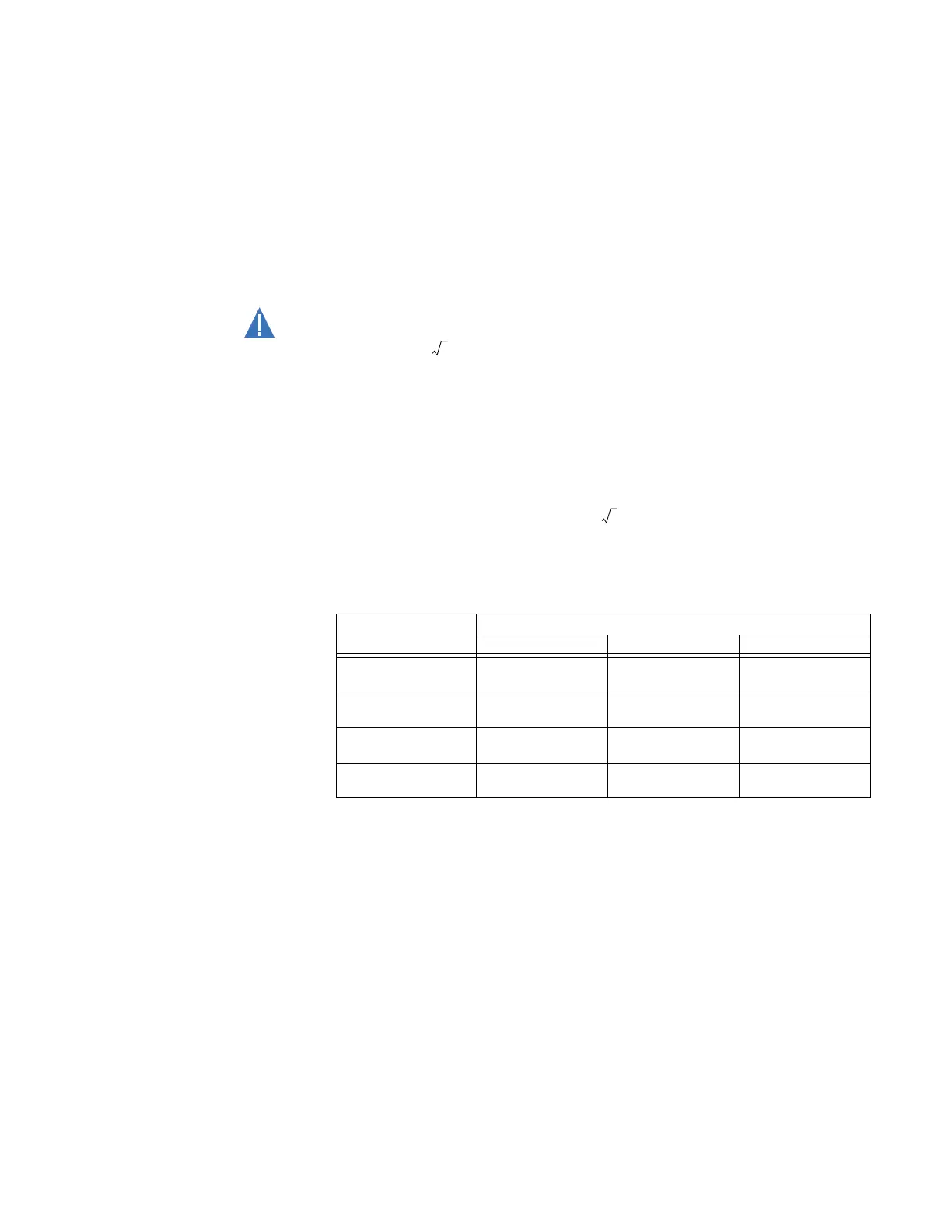
• LOAD LOSS AT RATED LOAD: Enter the load loss at rated load. This value is used for
calculation of harmonic derating factor, and in the Insulating Aging function. This is an
auto-ranging setpoint dependent on the
LOW VOLTAGE WINDING RATING value; see
ranges in the following table
• LOW VOLTAGE WINDING RATING: Enter the low voltage winding rating. This selection
affects the ranges of
WINDING 1(3) NOM ø-ø VOLTAGE, WINDING 1(3) RATED LOAD,
MINIMUM TAP POSITION VOLTAGE, and VOLTAGE INCREMENT PER TAP as shown in the
table above.
• RATED WINDING TEMP RISE: Determines the type of insulation; for use in the
computation of insulation aging.
• NO-LOAD LOSS: From the transformer data. It is required for insulation aging
calculations This is an auto-ranging setpoint dependent on the
LOW VOLTAGE
WINDING RATING
value; see ranges in the above table.
• TYPE OF COOLING: From Transformer data; required for insulation aging calculations.
• RATED TOP OIL RISE OVER AMBIENT: Required for insulation aging calculations
• XFMR THRML CAPACITY: Required for insulation aging calculations. Obtain from
transformer manufacturer
Setting Low voltage winding rating
above 5 kV 1 kV to 5 kV below 1 kV
MINIMUM TAP
POSITION VOLTAGE
0.1 to 2000.0 kV
in steps of 0.1
0.01 to 200.00 kV
in steps of 0.01
0.001 to 20.000 kV
in steps of 0.001
VOLTAGE
INCREMENT PER TAP
0.01 to 20.00 kV
in steps of 0.01
0.001 to 2.000 kV
in steps of 0.001
0.0001 to 0.2000 kV
in steps of 0.0001
LOAD LOSS AT
RATED LOAD
1 to 20000 kW
in steps of 0.1
0.1 to 2000.0 kW
in steps of 0.01
0.01 to 200.00 kW
in steps of 0.001
NO LOAD LOSS
0.1 to 2000.0 kW
in steps of 1
0.01 to 200.00 kW
in steps of 0.1
0.001 to 20.000 kW in
steps of 0.01