CHAPTER 5: SETPOINTS S2 SYSTEM SETUP
745 TRANSFORMER PROTECTION SYSTEM – INSTRUCTION MANUAL 5–37
Note
This setting is visible only for a 3W transformer.
Note
Whenever transformer type is changed (particularly from 2 W to 3 W) "ground input
selection" setting should be cross-checked.
• WINDING 1(3) GROUND CT PRIMARY: Enter the ground CT primary current rating of
the current transformers connected in the winding 1(3) neutral to ground path. The CT
secondary current rating must match the relay ground current input rating indicated.
• WINDING 1(3) SERIES 3-Φ RESISTANCE: Enter the series three-phase resistance of the
winding (that is, the sum of the resistance of each of the three phases for the winding).
This value is normally only available from the transformer manufacturer’s test report,
and is used in the 745 for calculation of harmonic derating factor.
5.4.4 Onload Tap Changer
PATH: SETPOINTS S2 SYSTEM SETUP ONLOAD TAP CHANGER
This section contains the settings to configure the tap position input. The 745 accepts a
resistive input from the tap changer control circuitry, which is used in the 745 to
dynamically correct for CT ratio mismatch based on the dynamically changing voltage
ratio of the transformer. Thus, the percent differential function of the device can be set for
greater sensitivity. See Dynamic CT Ratio Mismatch Correction on page 5–6 for more details
on the tap position input.
• WINDING WITH TAP CHANGER: Enter the winding with the tap changer. Enter 'None'
for a transformer with no onload tap changer, or to disable this feature.
• NUMBER OF TAP POSITIONS: Enter the number of tap positions here.
• MINIMUM TAP POSITION VOLTAGE: Enter the voltage at the lowest tap position. This is
an auto-ranging setpoint dependent on
S2 SYSTEM SETUP TRANSFORMER LOW
VOLTAGE WINDING RATING
; see ranges in the table below.
• VOLTAGE INCREMENT PER TAP: Enter the voltage increment for each tap. The range is
affected by the setpoint. This is an auto-ranging setpoint dependent on the
S2 SYSTEM
SETUP
TRANSFORMER LOW VOLTAGE WINDING RATING value; see ranges in the
following table:
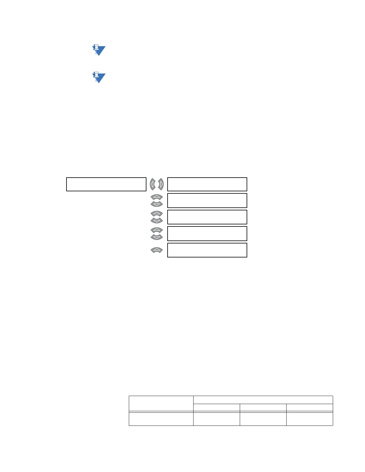
ONLOAD TAP []
CHANGER
WINDING WITH TAP
CHANGER: None
Range: None, Winding 1, Winding 2,
Winding 3
MESSAGE
NUMBER OF TAP
POSITIONS: 33
Range: 2 to 50 in steps of 1
MESSAGE
MINIMUM TAP POSITION
VOLTAGE: 61.0 kV
Range: Dependent on LOW VOLTAGE
WINDING RATING; see below.
MESSAGE
VOLTAGE INCREMENT
PER TAP: 0.50 kV
Range: Dependent on LOW VOLTAGE
WINDING RATING; see below.
MESSAGE
RESISTANCE INCREMENT
PER TAP: 33 Ω
Range: 10 to 500 Ω in steps of 1
Setting Low voltage winding rating value
above 5 kV 1 kV to 5 kV below 1 kV
MINIMUM TAP POSITION
VOLTAGE
0.1 to 2000.0 kV in
steps of 0.1
0.01 to 200.00 kV in
steps of 0.01
0.001 to 20.000 kV
in steps of 0.001