CHAPTER 5: SETPOINTS S4 ELEMENTS
745 TRANSFORMER PROTECTION SYSTEM – INSTRUCTION MANUAL 5–53
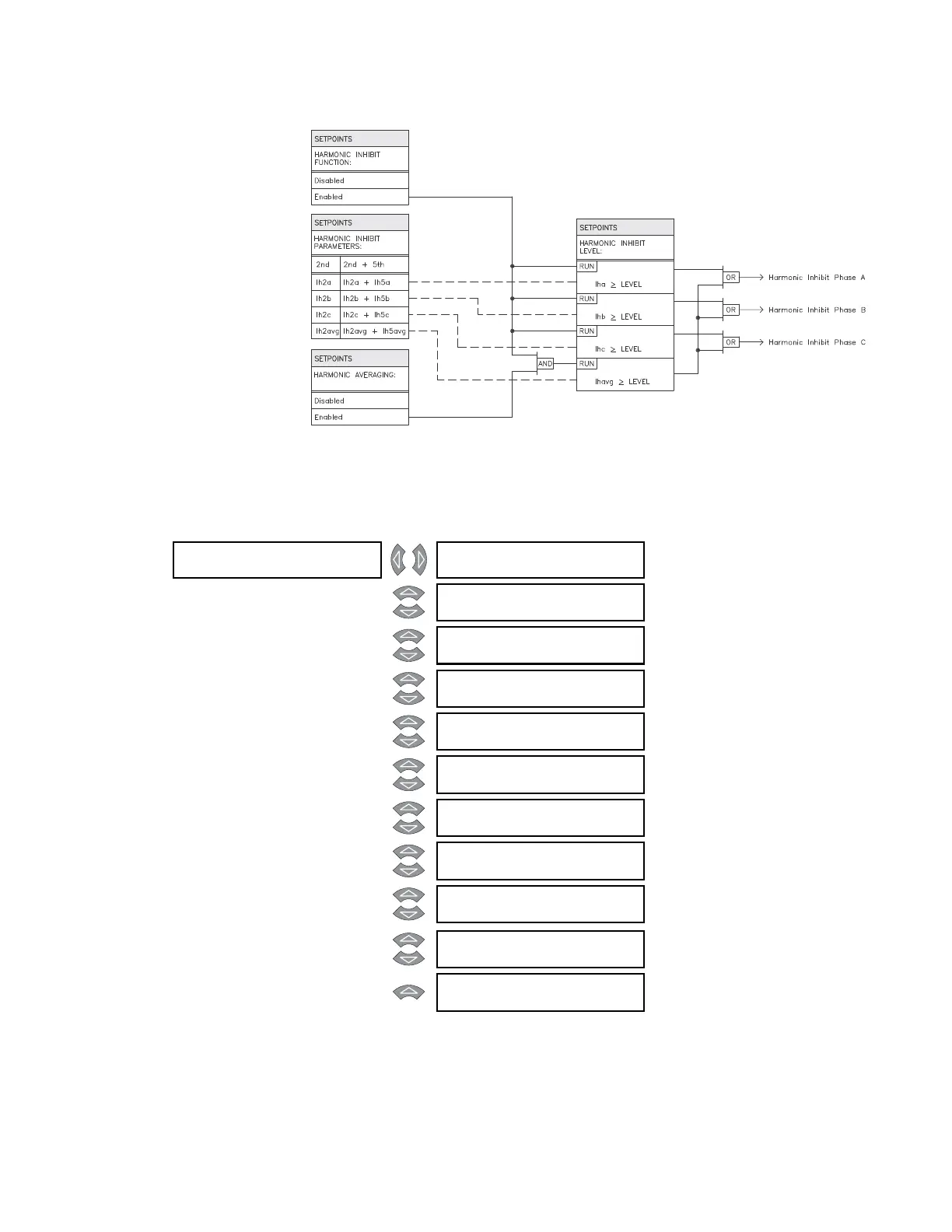
FIGURE 5–10: Harmonic inhibit scheme logic
5.6.3.4 Energization inhibit
PATH: SETPOINTS S4 ELEMENTS DIFFERENTIAL ENERGIZATION INHIBIT
Over and above the standard harmonic inhibit feature programmed above, the 745
contains a harmonic inhibit feature which is in service only during energization and/or
sympathetic inrush. De-energization and energization of the transformer is detected by
any of the following three methods:
ENERGIZATION []
INHIBIT
ENERGIZATION INHIBIT
FUNCTION: Enabled
Range: Enabled, Disabled
MESSAGE
ENERGIZATION INHIBIT
PARAMETERS: 2nd
Range: 2nd, 2nd + 5th
MESSAGE
HARMONIC AVERAGING:
Enabled
Range: Enabled, Disabled
MESSAGE
ENERGIZATION INHIBIT
LEVEL: 20.0% f0
Range: 0.1 to 65.0% f
0
in steps of 0.1
MESSAGE
ENERGIZATION INHIBIT
DURATION: 0.10 s
Range: 0.05 to 600.00 s in steps of 0.01
MESSAGE
ENERGIZATION SENSING
BY CURRENT: Enabled
Range: Enabled, Disabled
MESSAGE
MINIMUM ENERGIZATION
CURRENT: 0.10 x CT
Range: 0.10 to 0.50 x CT in steps of
0.01
MESSAGE
ENERGIZATION SENSING
BY VOLTAGE: Disabled
Range: Enabled, Disabled. Seen only if
Voltage Sensing is enabled.
MESSAGE
MINIMUM ENERGIZATION
VOLTAGE: 0.85 x VT
Range: 0.50 to 0.99 x VT in steps of
0.01. Seen only if Voltage
Sensing is enabled.
MESSAGE
BREAKERS ARE OPEN
SIGNAL: Disabled
Range: Logic Input 1 to 16, Disabled
MESSAGE
PARALL XFMR BRKR CLS
SIGNAL: Disabled
Range: Logic Input 1 to 16, Disabled