5–56 745 TRANSFORMER PROTECTION SYSTEM – INSTRUCTION MANUAL
S4 ELEMENTS CHAPTER 5: SETPOINTS
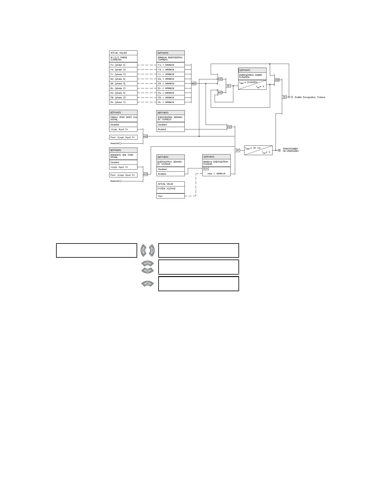
FIGURE 5–12: Energization sensing scheme logic
5.6.3.5 Fifth harmonic inhibit
PATH: SETPOINTS S4 ELEMENTS DIFFERENTIAL 5th HARM INHIBIT
The 5
th
harmonic inhibit feature of the percent differential element allows inhibiting the
percent differential during intentional overexcitation of the system. This feature inhibits the
percent differential element in a particular phase if the 5
th
harmonic of the same phase
exceeds the harmonic inhibit level setting. With harmonic averaging enabled, all three
phases are inhibited if the three-phase average of the 5
th
harmonic exceeds the level
setting.
• HARMONIC AVERAGING: Select “Enabled” to use the three-phase average of the 5th
harmonic current against the harmonic inhibit setting.
5th HARM []
INHIBIT
5th HARMONIC INHIBIT
FUNCTION: Enabled
Range: Enabled, Disabled
MESSAGE
HARMONIC AVERAGING:
Disabled
Range: 0.10 to 0.50 x CT in steps of
0.01
MESSAGE
5th HARMONIC INHIBIT
LEVEL: 10.0% fo
Range: 0.1 to 65.0% f
0
in steps of 0.1