5–84 745 TRANSFORMER PROTECTION SYSTEM – INSTRUCTION MANUAL
S4 ELEMENTS CHAPTER 5: SETPOINTS
This section contains the settings to configure the overexcitation monitoring elements.
Included are a 5th harmonic level, and two volts-per-hertz elements, each with a pickup
level and a time delay.
5.6.11.2 Fifth Harmonic Level
PATH: SETPOINTS S4 ELEMENTS OVEREXCITATION 5th HARMONIC LEVEL
• MINIMUM OPERATING CURRENT: Enter the minimum value of current (in units of relay
nominal current) required to allow the 5th harmonic level element to operate.
• 5TH HARMONIC LEVEL PICKUP: Enter the 5th harmonic current (in %ƒ
0
) above which
the 5th harmonic level element will pickup and start the delay timer.
• 5TH HARMONIC LEVEL DELAY: Enter the time that the 5th harmonic current must
remain above the pickup level before the element operates.
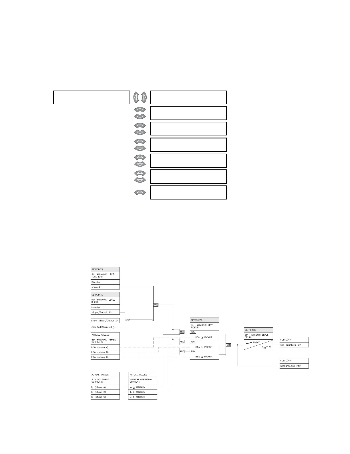
FIGURE 5–33: 5th harmonic level scheme logic
5th HARMONIC []
LEVEL
5th HARMONIC LEVEL
FUNCTION: Disabled
Range: Enabled, Disabled
MESSAGE
5th HARMONIC LEVEL
RLYS (1-8): --------
Range: 1 to 8
MESSAGE
5th HARMONIC LEVEL
TARGET: Self-Reset
Range: Self-Reset, Latched, None
MESSAGE
MINIMUM OPERATING
CURRENT: 0.10 x CT
Range: 0.03 to 1.00 x CT in steps of
0.01
MESSAGE
5th HARMONIC LEVEL
PICKUP: 10.0% fo
Range: 0.1 to 99.9% f
0
in steps of 0.1
MESSAGE
5th HARMONIC LEVEL
DE L AY: 1 0 s
Range: 0 to 60000 s in steps of 1
MESSAGE
5th HARMONIC LEVEL
BLOCK: Disabled
Range: Logc Inpt 1 to 16, Virt Inpt 1 to
16, Output Rly 2 to 8, SelfTest
Rly, Vir Outpt 1 to 5, Disabled