5–86 745 TRANSFORMER PROTECTION SYSTEM – INSTRUCTION MANUAL
S4 ELEMENTS CHAPTER 5: SETPOINTS
where: T = operate time (in seconds)
D = delay setpoint (in seconds)
V = fundamental RMS value of voltage (V)
F = frequency of voltage signal (Hz)
Pickup = volts per hertz pickup setpoint (V/Hz)
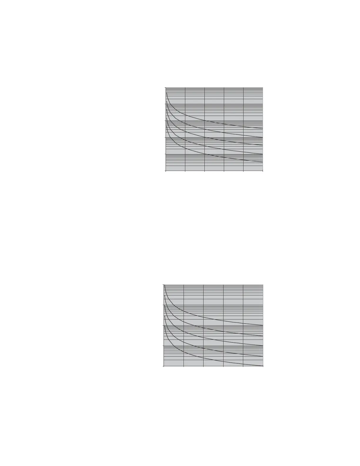
FIGURE 5–34: Volts per hertz curve 1
The curve for the inverse curve 2 shape is derived from the formula:
(EQ 5.13)
where: T = operate time (in seconds)
D = delay setpoint (in seconds)
V = fundamental RMS value of voltage (V)
F = frequency of voltage signal (Hz)
Pickup = volts per hertz pickup setpoint (V/Hz)
FIGURE 5–35: Volts per hertz curve 2
0.01
0.1
1
10
100
1000
1.00 1.20 1.40 1.60 1.80 2.00
Multiples of Volts/Hertz Pickup
Time
Delay
Setting
ò
10
3
1
0.3
0.1
Time to Trip (seconds)
T
D
VF⁄
Pickup
----------------
1–
--------------------------
= when
V
F
---
Pickup>
0.1
1
10
100
1000
1.00 1.20 1.40 1.60 1.80 2.00
Multiples of Volts/Hertz Pickup
Time
Delay
Setting
10
3
1
0.3
0.1
Time to Trip (seconds)