5–94 745 TRANSFORMER PROTECTION SYSTEM – INSTRUCTION MANUAL
S4 ELEMENTS CHAPTER 5: SETPOINTS
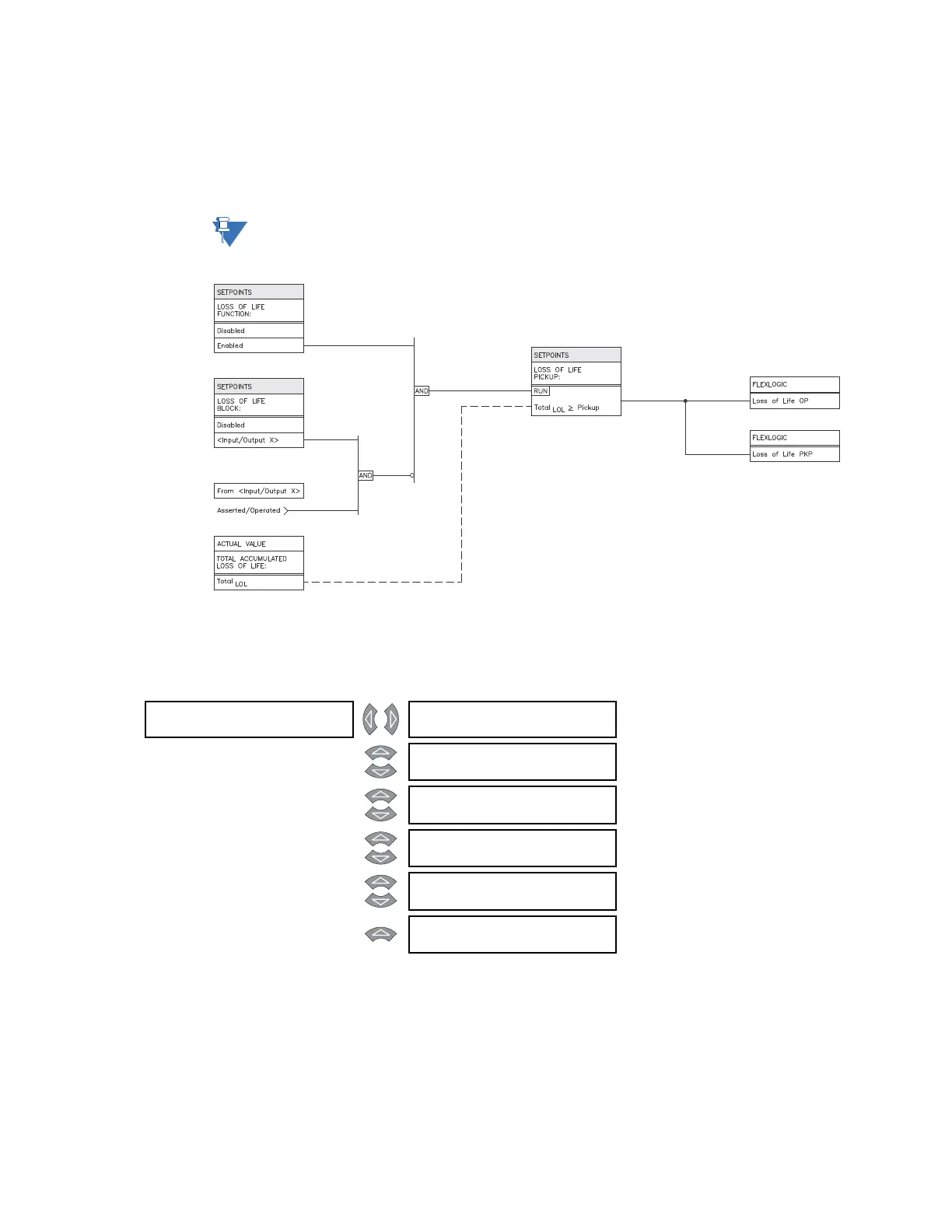
Enter the expended life, in hours, required for operation of the element in the LOSS OF LIFE
PICKUP
setpoint. This setting should be above the total life of the transformer, in hours. As
an example, for a 15-year transformer, the total number of hours would be 13140 × 10 =
131400 hours.
Note
The actual values are only displayed if the loss of life option is installed and the
ambient temperature is enabled.
FIGURE 5–42: Loss-of-life scheme logic
5.6.14 Analog Input Level
PATH: SETPOINTS S4 ELEMENTS ANALOG INPUT ANALOG LEVEL 1(2)
The 745 can monitor any external quantity, such as bus voltage, battery voltage, etc., via a
general purpose auxiliary current input called the analog input. Any one of the standard
transducer output ranges 0to1 mA, 0to5 mA, 4to20 mA, or 0to20 mA can be
connected to the analog input terminals. The analog input is configured in
S2 SYSTEM
SETUP
ANALOG INPUT and the actual values displayed in A2 METERING ANALOG
INPUT
.
ANALOG LEVEL 1 [] ANALOG INPUT LEVEL 1
FUNCTION: Disabled
Range: Enabled, Disabled
MESSAGE
ANALOG INPUT LEVEL 1
RLYS (1-8): --------
Range: 1 to 8
MESSAGE
ANALOG INPUT LEVEL 1
TARGET: Self-Reset
Range: Self-Reset, Latched, None
MESSAGE
ANALOG INPUT LEVEL 1
PICKUP: 10 μA
Range: 1 to 65000 μA in steps of 1
MESSAGE
ANALOG INPUT LEVEL 1
DE L AY: 5 0 s
Range: 0 to 60000 s in steps of 1
MESSAGE
ANALOG INPUT LEVEL 1
BLOCK: Disabled
Range: Logc Inpt 1 to 16, Virt Inpt 1 to
16, Output Rly 2 to 8, SelfTest
Rly, Vir Outpt 1 to 5, Disabled