5–110 745 TRANSFORMER PROTECTION SYSTEM – INSTRUCTION MANUAL
S6 TESTING CHAPTER 5: SETPOINTS
• START PLAYBACK MODE SIGNAL: Select any logic input which, when asserted, initiates
playback mode simulation. This signal has an effect only if the 745 is initially in
prefault mode.
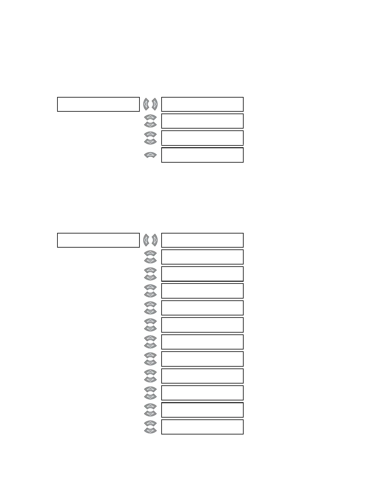
5.8.4.3 Prefault Values
PATH: SETPOINTS S6 TESTING SIMULATION PREFAULT VALUES
• W1 to W3 PHASE ABC CURRENT MAGNITUDE: Enter the winding 1(3) phase current
magnitude (in terms of the winding full load current) while in prefault mode.
• VOLTAGE INPUT MAGNITUDE: Enter the voltage magnitude (in terms of the nominal
VT secondary voltage) while in prefault mode.
5.8.4.4 Fault Values
PATH: SETPOINTS S6 TESTING SIMULATION FAULT VALUES
PREFAULT []
VA L U E S
W1 PHASE ABC CURRENT
MAGNITUDE: 1.0 x CT
Range: 0.0 to 40.0 x CT in steps of 0.1
MESSAGE
W2 PHASE ABC CURRENT
MAGNITUDE: 1.0 x CT
Range: 0.0 to 40.0 x CT in steps of 0.1
MESSAGE
W3 PHASE ABC CURRENT
MAGNITUDE: 1.0 x CT
Range: 0.0 to 40.0 x CT in steps of 0.1
MESSAGE
VOLTAGE INPUT
MAGNITUDE: 1.0 x VT
Range: 0.0 to 2.0 x VT in steps of 0.1
FAULT []
VA L U E S
W1 PHASE A CURRENT
MAGNITUDE: 1.0 x CT
Range: 0.0 to 40.0 x CT in steps of 0.1
MESSAGE
W1 PHASE A CURRENT
ANGLE: 0°
Range: 0 to 359° in steps of 1
MESSAGE
W1 PHASE B CURRENT
MAGNITUDE: 1.0 x CT
Range: 0.0 to 40.0 x CT in steps of 0.1
MESSAGE
W1 PHASE B CURRENT
ANGLE: 0°
Range: 0 to 359° in steps of 1
MESSAGE
W1 PHASE C CURRENT
MAGNITUDE: 1.0 x CT
Range: 0.0 to 40.0 x CT in steps of 0.1
MESSAGE
W1 PHASE C CURRENT
ANGLE: 0°
Range: 0 to 359° in steps of 1
MESSAGE
W1 GROUND CURRENT
MAGNITUDE: 0.0 x CT
Range: 0.0 to 40.0 x CT in steps of 0.1
MESSAGE
W1 GROUND CURRENT
ANGLE: 0°
Range: 0 to 359° in steps of 1
MESSAGE
W2 PHASE A CURRENT
MAGNITUDE: 1.0 x CT
Range: 0.0 to 40.0 x CT in steps of 0.1
MESSAGE
W2 PHASE A CURRENT
ANGLE: 0°
Range: 0 to 359° in steps of 1
MESSAGE
W2 PHASE B CURRENT
MAGNITUDE: 1.0 x CT
Range: 0.0 to 40.0 x CT in steps of 0.1
MESSAGE
W2 PHASE B CURRENT
ANGLE: 0°
Range: 0 to 359° in steps of 1