6–8 745 TRANSFORMER PROTECTION SYSTEM – INSTRUCTION MANUAL
A2 METERING CHAPTER 6: ACTUAL VALUES
6.3.1.2 Winding Currents
PATH: ACTUAL VALUES
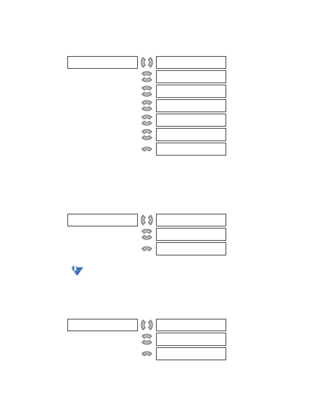
A2 METERING CURRENT W1(3) CURRENT
The fundamental frequency current magnitudes for winding 1 phases A, B, and C, neutral,
and ground are shown. The current angle for phase A is always set to 0° as it is used as
reference for all other currents, both measured and derived. The maximum specified load
and average phase current are also shown for the specified winding.
6.3.1.3 Positive-sequence Current
PATH: ACTUAL VALUES
A2 METERING CURRENT POSITIVE SEQUENCE
Note
All positive-, negative-, and zero- sequence component phase angles are referenced to
the winding 1 phase A current
The positive-sequence current magnitudes and phase values for windings 1, 2, and 3 are
shown here.
6.3.1.4 Negative-sequence Current
PATH: ACTUAL VALUES
A2 METERING CURRENT NEGATIVE SEQUENCE
W1 CURRENT [] W1 PHASE A CURRENT:
0 A at 0° Lag
MESSAGE
W1 PHASE B CURRENT:
0 A at 0° Lag
MESSAGE
W1 PHASE C CURRENT:
0 A at 0° Lag
MESSAGE
W1 NEUTRAL CURRENT:
0 A at 0° Lag
MESSAGE
W1 GROUND CURRENT:
0 A at 0° Lag
MESSAGE
WINDING 1 LOADING:
0% of rated load
MESSAGE
W1 AVERAGE PHASE
CURRENT: 0 A
POSITIVE []
SEQUENCE
W1 POS SEQ CURRENT:
0 A at 0° Lag
MESSAGE
W2 POS SEQ CURRENT:
0 A at 0° Lag
MESSAGE
W3 POS SEQ CURRENT:
0 A at 0° Lag
NEGATIVE []
SEQUENCE
W1 NEG SEQ CURRENT:
0 A at 0° Lag
MESSAGE
W2 NEG SEQ CURRENT:
0 A at 0° Lag
MESSAGE
W3 NEG SEQ CURRENT:
0 A at 0° Lag